397152/E
17
Connectingthetranspondertoexternal
powerandrespondersignals
Thetranspondercanalsobeusedasaresponderunit.
Prerequisites
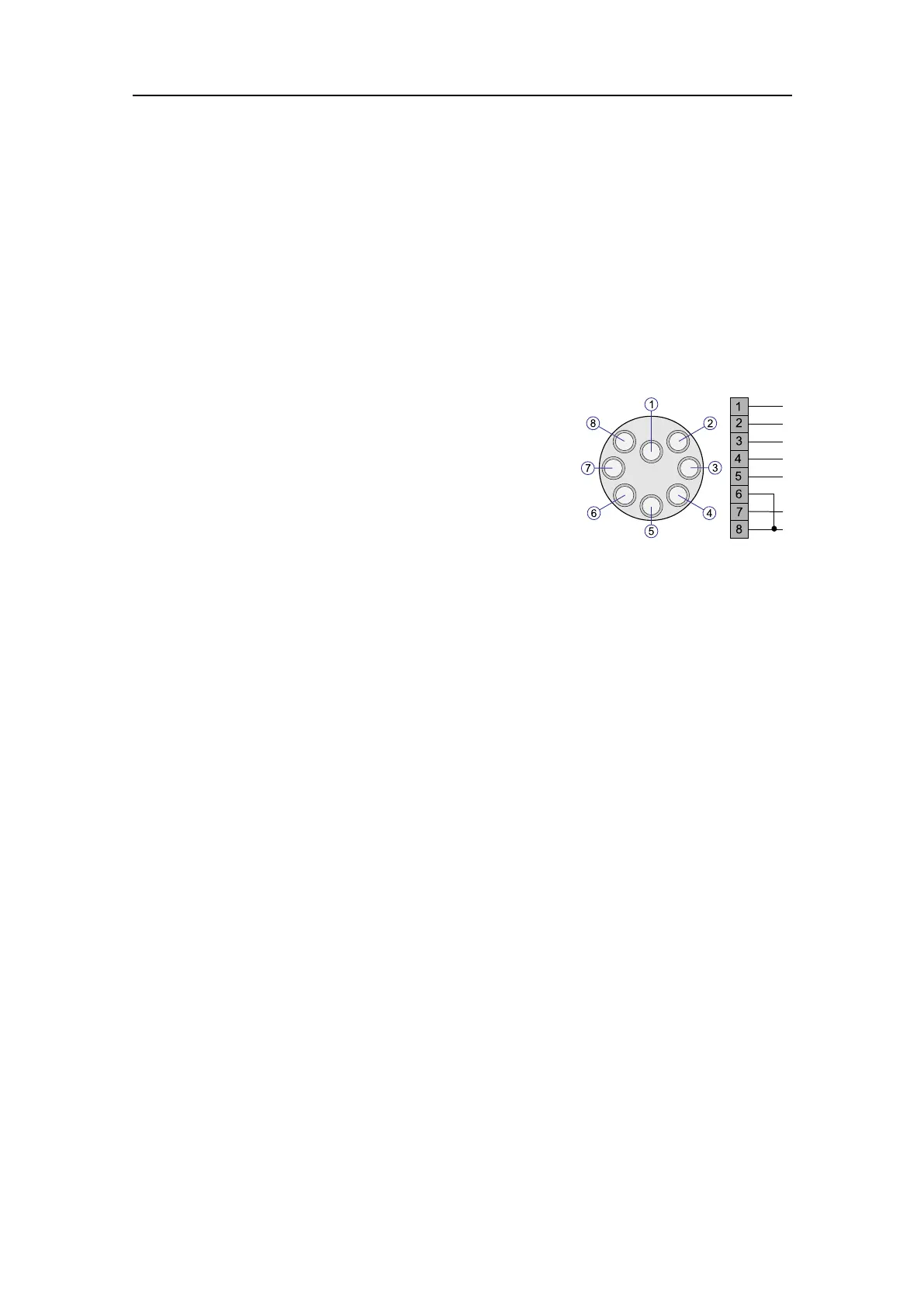
Thetranspondermustbechargedbeforeuse.Thisisthepincongurationforamale
connector,asseentowardstheconnector(faceview).
1
2
3
4Respondertrigger+
5Respondertrigger-
6On/Off
7Externalpower(24VDC)
8Ground
Procedure
1Usethecablewithpartnumber402462fromKongsberg.
2Connectwire6and8inthepigtail(theON/OFFfunction).
When6-8arelinked,thetransponderisON.
Withnoconnectionbetween6-8,thetransponderisOFF.
3Makesurethattheexternalpowersupply24VDCisbetween20and28VDC.
4Checktherespondertriggersignal.
5SwitchONtheunitbyinsertingtheexternalpower/respondercable.
Furtherrequirements
ItisrecommendedtotestthetransponderwiththeTestandCongurationunit(TTC)to
makesureitisworkingproperlybeforeoperation.
Gettingstarted