KTD-N0882-I Page 53 Internal Connectors
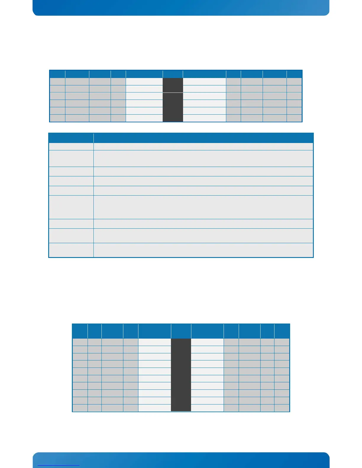
7.14 SPI Connector (SPI_HEAD)
The SPI Connector is normally not used. If however a SPI BIOS is connected via the SPI Connector then the
board will attempt to boot from it.
7.15 LPC Connector (J30)
The LPC connector (Flex board only) is in general unsupported. Only under special circumstances may the
LPC interface be of interest.
Signal Description
3.3V Standby Voltage power line. Normally output power, but when Motherboard is
turned off then the on-board SPI Flash can be 3.3V power sourced via this pin.
CS0# CS0# Chip Select 0, active low.
ADDIN ADDIN input signal must be NC.
MOSI Master Output, Slave Input.
ISOLATE#
The ISOLATE# input, active low, is normally NC, but must be connected to GND when
SPI flash. Power Supply to the Motherboard must be turned off when
loading SPI flash. The pull up resistor is connected via diode to 5VSB.
MISO
Master Input, Slave Output
SPI_IO2_#WP
SPI Data I/O: A bidirectional signal used to support Dual IO Fast Read, Quad IO Fast Read
and Quad Output Fast Read modes. The signal is not used in Dual Output Fast Read mode.
SPI Data I/O: A bidirectional signal used to support Dual IO Fast Read, Quad IO Fast Read
and Quad Output Fast Read modes. The signal is not used in Dual Output Fast Read mode.
Ioh/Iol Type Signal PIN Signal Type Ioh/Iol