11
Rear panel
Message windows
MESSAGE WINDOWS
Sometimes, amessagemight appear inthedisplay,warning
aboutanerrororanincorrectoperation:
PressENTERorEXITtoexitoneofthesewindows.
Other messages ask for an answer, as in the “A r e you sure”
windowbelow:
PressENTER/YESforYes,orEXIT/NOforNo.
SYMBOLS AND ICONS
Many icons and symbols, on the custom display, show the
statusofaparameterorthedisplaycontent.
Realtime/Keyboardtrack
(Upper1–3,Lower).
Drumtrack(Styletrackview).
Percussiontrack(Styletrackview).
GroupedDrumandPercussiontracks.
Basstrack(Styletrackview).
Grouped accompaniment tracks. This symbol
indicates the five grouped accompaniment
tracks(Acc1–5).
Accompanimenttracks(S
tyletrackvi
ew).
Sequencertracks.
Selectedtrackorparameter.Whenthissymbol
appears, youcan execute any available opera‐
tionontheselecteditem.
(noicon) Thetrackisinmute,andcan’tplayonthekey‐
board.
GRAYED-OUT NON-AVAILABLE
PARAMETERS
Currentlynon‐availableparametersarenowshownin“gray”
inthe display,i.e.witha“ghost”texture.Hereisanexample
ofagrayed‐outparameter,comparedtoanormalparameter:
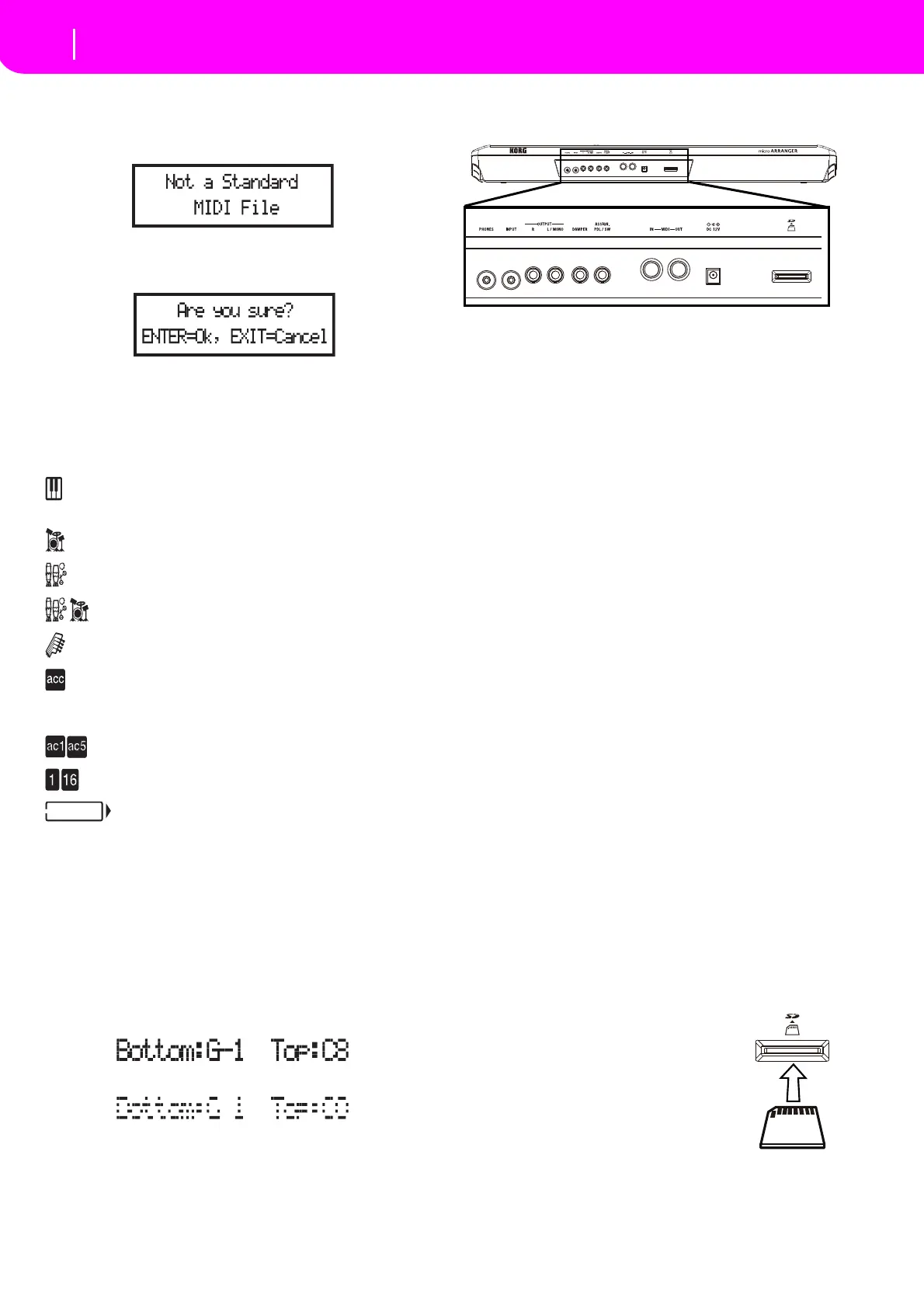
5. REAR PANEL
1 PHONES
Use this jack to connect a pair of headphones. You can use
headphoneswithanimpedanceof16–200Ω(50Ωsuggested).
Useaheadphonedistributortoconnectmorethanonepairof
headphones.
2INPUT
Usetheseunbalancedconnectorstoinputanotherkeyboard/
synthesizer, a (non‐powered) mixer’s output, or a CD/tape
player(lineimpedance).Thesignalisautomaticallyroutedto
thespeakers,theAudioOutputsandthePhones.
3OUTPUTS
Use these unbalanced connectors to send the audio signal
(sound)toamixer,aPA system,aset ofpoweredmonitors,
or your hi‐fi system.Set theoutput level with the MASTER
VOLUMEslider.
4DAMPER
UsethistoconnectaDamperpedal,liketheKORGPS1,PS3
orDS1H.
5 ASSIGN. PDL/SW
Usethistoconnectacontinuousorfootswitchpedal,likethe
KORGEXP2orXVP10.
6 MIDI interface
TheMIDIinterfaceallowsyourmicroARRANGERtobecon‐
nectedtoanexternalcontroller(masterkeyboard,MIDIgui‐
tar,windcontroller,MIDIaccordion…),toanexpander,orto
acomputerrunningasequenceroraneditor.
IN ThisconnectorreceivesMIDIdatafromacom‐
puteror a controller. Connectit to anexternal
controll
er’sorcomputer’sMIDIOUT.
OUT This connector sends MIDI data generatedby
the microARRANGER’s keyboard, controllers,
and/ortheinternalsequencer.Connectittoan
expander’sorcomputer’sMIDIIN.
7 DC 12V (AC power adapter connector)
Plugthesuppliedpoweradapterintothisconnector.
8 SD Card Slot
ToinsertanSDcard(orSDHCcard),pushit
into the slot until it clicks into place. To
removetheSDcard,pushitin;thecardwill
popoutslightly,allowingyoutopullitout.
Note: Carefully read the ownerʹs manual that
camewithyourSD card,andobservetheinstruc‐
tionsre
gardingcareandhandling.
Note:Take caretoinserttheSDcardinthecor‐
rect direction and orientation, and be sure to
press it all the way into the slot. Do not use
excessiveforce.
Text in solid black
Text in gray
Connector
side