125
Sound Edit operating mode
Filter: Filter LFO
Reference
AMS (EG Alternate Modulation Source)
Selects the source that will control the depth and direction of the
effect that the time-varying changes produced by the filter EG
will have on the cutoff frequency of filters A and B. See “AMS
(Alternate Modulation Source) list” on page 136.
Int to A (Intensity to A)
Specifies the depth and direction of the effect that “AMS” will
have on filter A. For details on how this will apply, refer to “Int to
A (Intensity to A)”.
Int to B (Intensity to B)
Specifies the depth and direction of the effect that “AMS” will
have on filter B. For details on how this will apply, refer to “Int to
A (Intensity to A)”.
Note: The sum of the settings for “Velocity to A/B”, “Intensity to A/
B”, and “(AMS) Intensity to A/B” will determine the depth and
direction of the effect produced by the filter EG.
Filter A/B Modulation
AMS1 (Alternate Modulation Source 1 for filter A/B)
Selects the source that will control modulation of the filter A
cutoff frequency. See “AMS (Alternate Modulation Source) list”
on page 136.
Note: The filter B parameters will be displayed when “Filter Type”
on page 123 is Low Pass & High Pass.
Intensity (Intensity to AMS1)
Specifies the depth and direction of the effect that “AMS1” will
have.
When “AMS1” is JS X, a positive (+) value for this parameter will
cause the cutoff frequency to rise when the joystick is moved
toward the right, and fall when the joystick is moved toward the
left. With a negative (–) value for this parameter, the opposite
will occur.
This value is added to the setting of the Filter A “Frequency”.
AMS2 (Alternate Modulation Source 2 for filter A/B)
Selects the source that will control modulation of the filter A
cutoff frequency (see “AMS (Alternate Modulation Source) list”
on page 136).
Intensity (Intensity to AMS2)
Specifies the depth and direction of the effect that the selected
source will have (see “Intensity (Intensity to AMS1)” on
page 125).
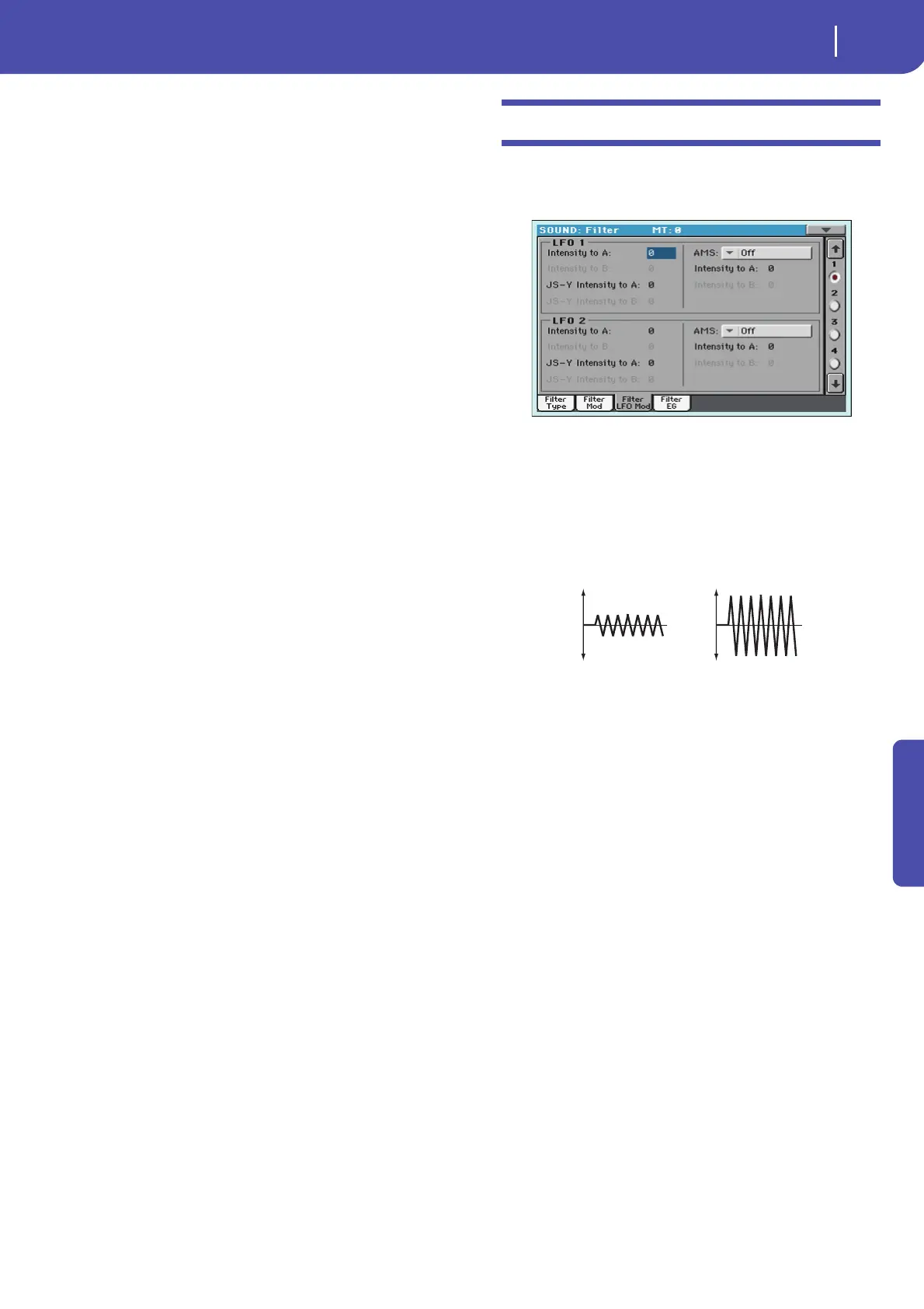
Filter: Filter LFO
Here you can use the filter LFO to apply cyclic modulation to the
cutoff frequency of the filter (for the selected oscillator) to create
cyclical changes in tone.
LFO 1
Intensity to A
Specifies the depth and direction of the modulation that LFO1
(set on “LFO: LFO1”) will have on the cutoff frequency of filter
A. Negative (–) settings will invert the phase.
-99…+99 Parameter value.
Intensity to B
Specify the depth and direction of the modulation that LFO1
will have on the cutoff frequency of filter B (see “Intensity to A”).
-99…+99 Parameter value.
JS (Joystick) –Y Intensity to A
By moving the joystick in the Y direction (toward yourself), you
can control the depth at which LFO1 modulates the cutoff fre-
quency of filter A. This parameter specifies the depth and direc-
tion of the control.
Higher settings of this parameter will produce greater increases
in the effect of LFO1 on the filter when the joystick is moved
toward yourself.
-99…+99 Parameter value.
JS (Joystick) –Y Intensity to B
By moving the joystick in the Y direction (toward yourself), you
can control the depth at which LFO1 modulates the cutoff fre-
quency of filter B. This parameter specifies the depth and direc-
tion of the control (see “JS (Joystick) –Y Intensity to A”).
AMS (Filter LFO1 Alternate Modulation Source)
Select a source that will control the depth and direction of cutoff
frequency change for both filters A and B. See “AMS (Alternate
Modulation Source) list”.
Change in cutoff
Low setting High setting
 Loading...