KR Electrical Defrost Unit Coolers (PN E108318_S) 28
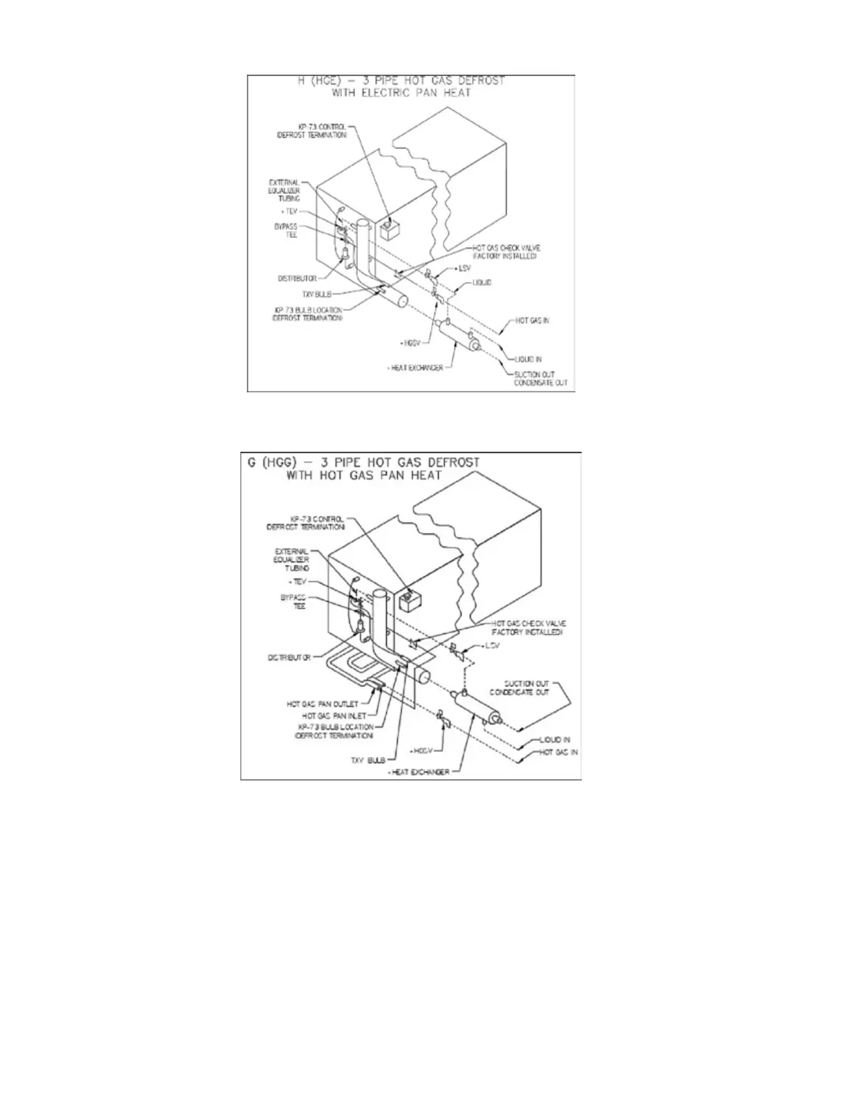
FIGURE 11A: MODEL H (HGE) – 3 PIPE HOT GAS DEFROST WITH ELECTRIC PAN HEAT
FIGURE 11B: MODEL G (HGG) – 3 PIPE HOT GAS DEFROST WITH HOT GAS PAN HEAT
9.2
MODELS G – 3 PIPE HOT GAS WITH GAS PAN HEAT AND K - 2 PIPE
KOOL GAS WITH GAS PAN HEAT
Three pipe hot gas defrost system - Distribute compressor discharge gas through a separate hot
gas line, controlled by a solenoid valve, through a check valve to the refrigerant distributor auxiliary
side connection. Defrost condensate and gas vapor is evaporated in a re-evaporator prior to return-
ing to the compressor through the suction line.
Two pipe cool gas defrost system - Distribute compressor discharge gas through the suction line
during defrost. Defrost condensate flows through the refrigerant distributor auxiliary side connection
and a check valve, bypassing the expansion valve and the liquid line solenoid valve into the liquid
line which is reduced in pressure.