29KR Electrical Defrost Unit Coolers (PN E108318_S)
The defrost cycle is field controller initiated and terminated.
Step A
Power is supplied to the unit cooler continuously.
Step B
In Case of H, defrost hot gas is supplied to the unit via liquid line and in Case of P, defrost Kool
Gas is supplied to the suction line. A factory mounted thermostat (Klixon) senses a rise in the coil temperature.
The SPDT control turns off the fan motors.
Step C
When the defrost is complete, the hot gas supply is stopped. The liquid line solenoid is energized,
and the coil temperature begins to fall.
Step D
The factory mounted thermostat senses the drop in coil temperature and closes the circuit to
the fan motors.
A separate SPDT thermostat (KP73) is provided in the coil which can provide a digital defrost termination
input.
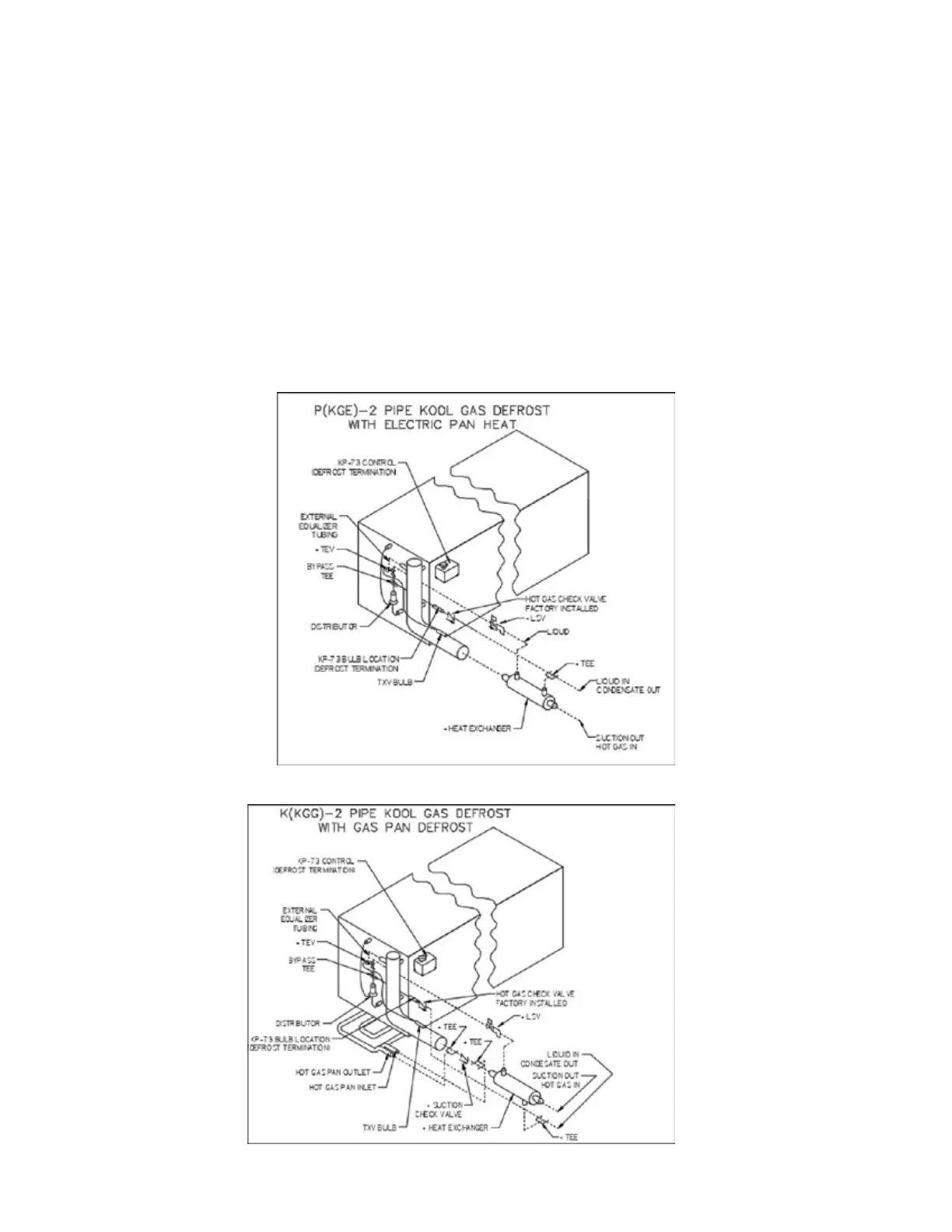
FIGURE 12A: MODEL P (KGE) – 2 PIPE KOOL GAS DEFROST WITH ELECTRIC PAN HEAT
FIGURE 12B: MODEL K (KGG) – 2 PIPE KOOL GAS DEFROST WITH GAS PAN DEFROST