33KR Electrical Defrost Unit Coolers (PN E108318_S)
In the case of variable speed motor coils, the jumper between the terminal A0+ and A should
be removed and then the aux contact from the single compressor unit be wired in series. Whenever the
compressor contactor is energized, the aux contact energizes, and NC contacts changes state to NO,
there by opening the analog 10V signal circuit. Whenever the controller sends the 10V signal, it goes
through the aux contact, and ensuring the compressor is on deactivating the analog signal circuit. When
the compressor is ON, the fans will never be able to modulate, though the controller is signaling the fans
to modulate.
10 PRE-STARTUP
After installation is complete, a review of the following items should be performed before the
system is placed into operation:
Check electrical connections, fan blade set screws, fan motors, guards, and all other fasteners
for tightness. Ensure the thermostatic expansion valve bulb is properly located, strapped, and insulated.
With the system operating, check the supply voltage. It must be within +/- 10% of the voltage marked on
the unit nameplate.
For electric defrost systems, check the defrost timer to see that is set for the correct time of day,
and that the starting pins have been installed (normally two per day). The defrost should be scheduled
for times when the freezer doors are not likely to be open.
To prevent overshooting the desired setting, only one turn of the stem should be made at a time.
As much as 30 minutes may be required for the new balance to take place after an adjustment is made.
Always tighten the adjusting stem packing nut and replace the seal cap tightly after the adjustment is
complete.
When the system is first started up, the box temperature is typically above the opening
temperature of the fan delay thermostat. The fans may remain off for an extended period. To prevent
this, it is permissible to install a temporary jumper wire between terminals “F” and “B” or “N” and “B”
depending on the unit wiring arrangement. Once the box temperature is below +25°F, the jumper wire
should be removed.
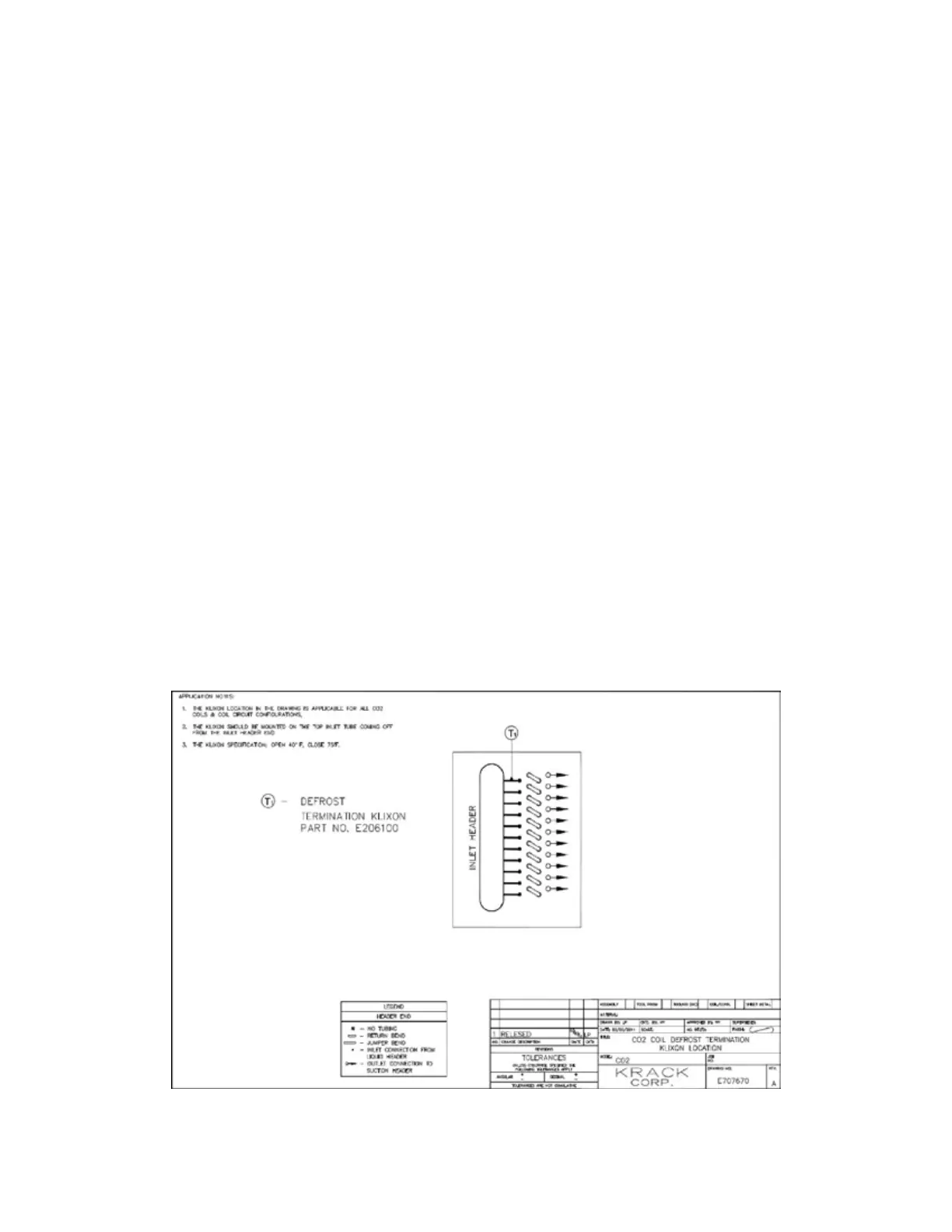
For units using Carbon Dioxide (R-744), the defrost termination thermostat is to be located on
the topmost inlet tube from the inlet header as shown in FIGURE 17.
FIGURE 17: DEFROST TERMINATION THERMOSTAT LOCATION FOR CARBON
DIOXIDE (R-744)