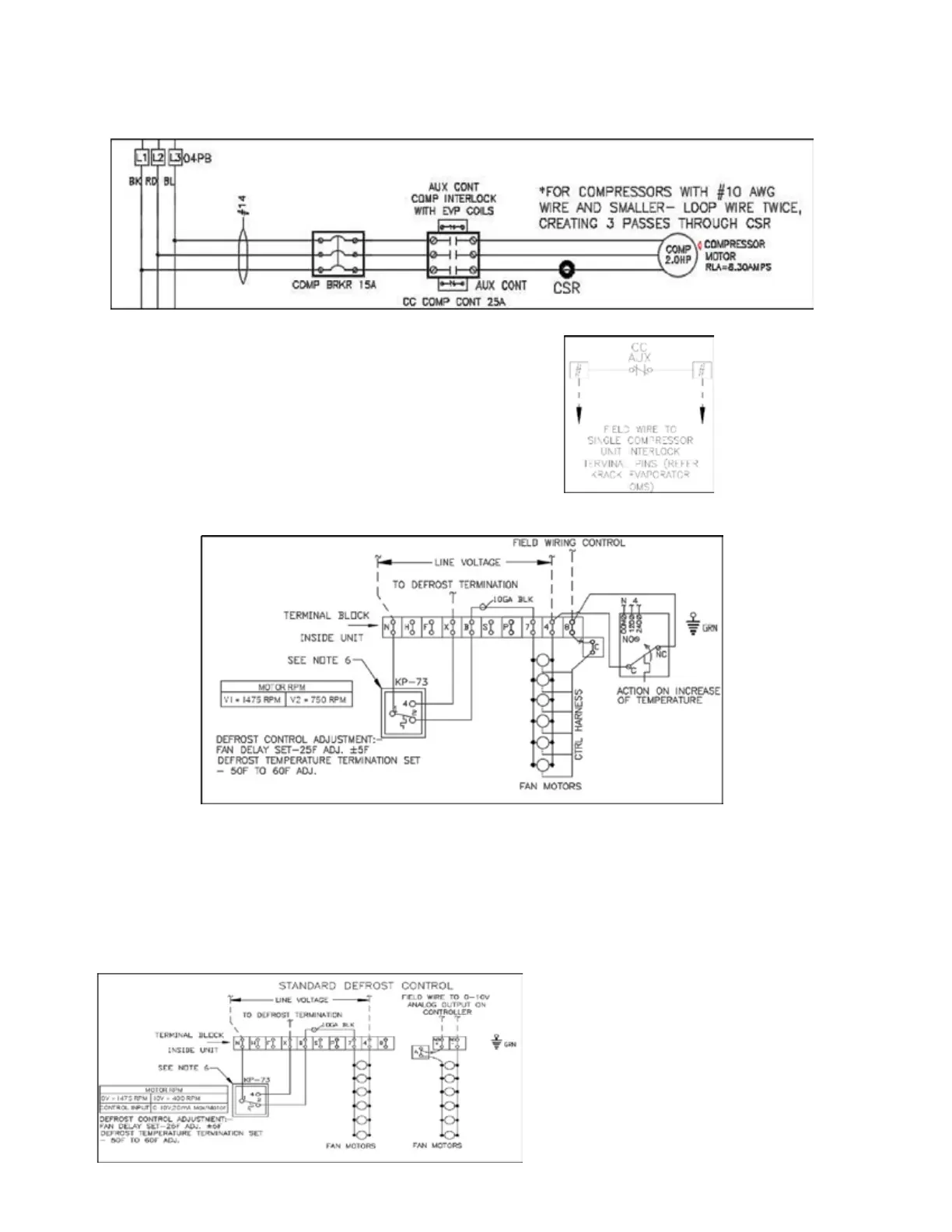
KR Electrical Defrost Unit Coolers (PN E108318_S) 32
Single compressor units use a contactor for compressor operation, a NC Aux contact attached to the main
contactor and will be used to interlock.
FIGURE 14 – SETUP IN SINGLE COMPRESSOR UNIT - (COMPRESSOR INTERLOCK)
Aux contact in Single compressor unit wired to terminal pins.
FIGURE 15: DUAL SPEED MOTOR EVAPORATER COILS – (MOTORS WITH CONTROL HARNESS)
Aux contact in Single compressor unit wired to terminal pin 8 and C.
In the case of a dual speed motor coil with control harness, the jumper between terminal 8 and C
should be removed and then the aux contact from single compressor unit wired in series. Whenever the
compressor contactor is energized, the Aux contact energizes, and NC contacts changes state to NO,
there by opening the control harness circuit. So, whenever compressor is on, fans will never go to low
speed mode, even getting signal from the room thermostat or filed controller.
FIGURE 16: VARIABLE SPEED MOTOR EVAPORATER COILS