8 Connection
8.2 Overview
8.2 Overview
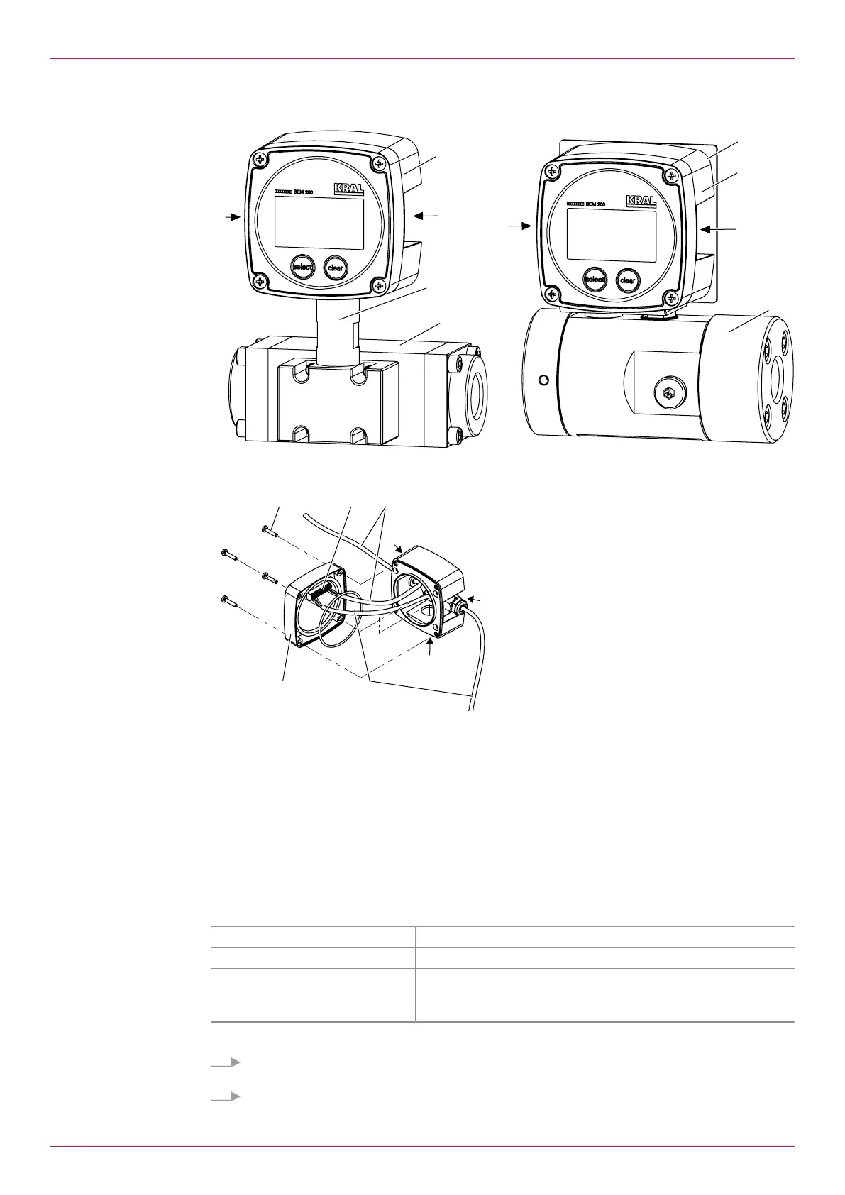
Fig.5: Electronic unit with OME (left) / Electronic unit with OMP (right)
Fig.6: Cable connections (example)
1 Electronic unit BEM 200 7 Connection panel
2 Pick up connection cable 8 Power supply connection cable
3 Connecting element A Opening 20.5 mm (connecting tube or cable
inlet)
4 Flow meter OME or OMP B Side opening 16.5 mm (cable entry)
5 Front cover C Side opening 16.5 mm (cable entry)
6 Phillips screw
8.3 Connecting the pick up
Personnel qualification: o Electrician
Personal protective equipment: o Work clothing
Aids: o Wire stripper
o Wire cutter
o Screwdriver
Note With flow meter OME or OMP the pick up is already connected.
1. For flow meters other than OME or OMP, use one of the side openingsB orC of the electronic
unit as the cable entry for the pick up connection.
2. Unscrew the Phillips screws6 and remove the front cover5 of the electronic unit.
12
OIE 24en-GB Edition 2022-01
Operating instructions