4 Technical data
4.2 Connection field
4.2 Connection field
10-30V
10-30V
+
–
impuls target
current target
NPN
...external source
+
mA
INTERNAL
EXTERNAL
+
+
10-30V
+
–
impuls target
current target
NPN
...external source
+
mA
INTERNAL
EXTERNAL
Voltage
Reg.
8.2V
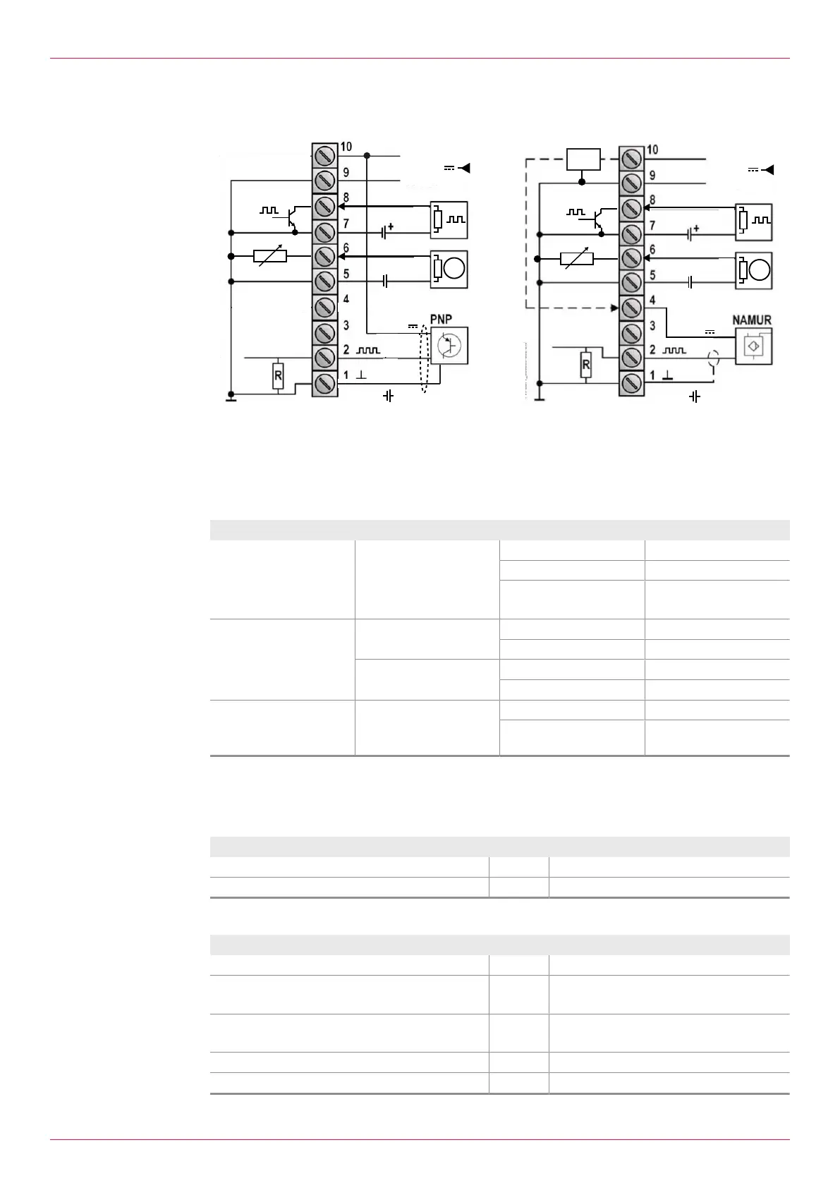
Fig.3: Connection panel for PNP sensors (left) / connection panel for NAMUR sensors (right)
4.3 Pin assignment
The following terminals are electrically connected internally:
o 1 + 5 + 7 + 9 = Gnd
Connection Function Terminal
PNP/NAMUR sensor Flow meter transducer Gnd 1
Signal 2
Sensor supply 10 (PNP)
4 (NAMUR)
Output Analog output Gnd 5
Signal 6
Pulse output Transistor - 7
Transistor + 8
Power supply Electronic unit Gnd 9
Power supply 10 –
30VDC
10
4.4 Connection data
4.4.1 Supply
Parameter Unit Value
Power supply, type PD [VDC] 10...30
Power consumption max. [W] 0.625
4.4.2 Pulse input
Parameter Unit Value
Frequency min. [Hz] 0.1...10, adjustable (= 1/gate time)
Frequency max. [kHz] 6 (PNP)
4 (NAMUR)
Input impedance [kΩ] 47 (PNP, pull-down resistor)
0.82 (NAMUR, pull-down resistor)
Level high [V] >6.3
Level low [V] <2.5
6
OIE 24en-GB Edition 2022-01
Operating instructions