Do you have a question about the KRAL BEM 500 and is the answer not in the manual?
Instructions are part of the product and must be kept for future reference. Observe associated documents.
Instructions are intended for personnel working with the product, operator-owners, and qualified personnel.
Lists related documents such as declaration of conformity, flowmeter instructions, calibration certificates, etc.
Explains danger levels, danger signs, and symbols used in the document for clear communication.
Unit for use with KRAL flowmeter within specified operating limits. Avoid misuse.
Any use beyond proper operation or intended limits is considered misuse.
Key safety instructions to observe: read manual, qualified personnel, PPE, observe other manuals.
Provides a visual representation of the unit's dimensions and a table with specific measurements.
Details about the text display, updating rate, illumination, contrast, and language options.
Information on electrical connections, including power supply and terminal types.
Diagram and description of the electronic unit's termination panel, showing terminal assignments.
Detailed table mapping components to their respective terminal pins for various functions.
Specifies operating and storage temperatures, humidity, vibration, shock, isolation, and protection ratings.
Refers to separate documentation for technical data of accessories.
Explains how the electronic unit works with flowmeters, K-factors, and pulse evaluation.
Details Modbus interface variables, data, and values for communication.
Lists the components included with the electronic unit.
Instructions for unpacking, checking for damage, and reporting issues.
Safety instructions for installation and removal, emphasizing work by electricians and not disassembling the unit.
Step-by-step guide for mounting the unit in a control cabinet, including requirements.
Instructions for wall mounting using a universal mount accessory.
Guide for mounting the unit on a pipe or flowmeter using a universal mount and fixing kit.
Safety instructions for connection work, stressing electricians, shielded lines, and correct power supply.
Step-by-step guide for connecting cables to tension spring terminals, with safety warnings.
Instructions for connecting sensors, including precautions and resistance checks.
Instructions for connecting outputs, with critical safety warnings about hazardous potentials.
Step-by-step guide for connecting the power supply, with important attention notices and requirements.
Procedures for installation, electrical installation, and function testing before commissioning.
Safety warnings and procedure for safely taking the unit out of operation.
Lists abbreviations, units, and details on pulse signals for operation.
Explains the function of each button and key combinations for operating the unit.
Covers general operating steps, password management, changing values, and units.
Overview of the menu structure, listing display and general settings categories.
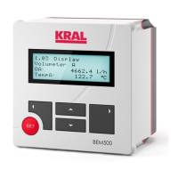
Describes the start message displayed upon switching on the unit.
Details various display items like serial number, consumption, totals, flow, and temperature.
Covers settings for password, mode selection, reference temperature, and unit settings.
Configures analog/pulse outputs, relay functions, bypass, and Modbus address.
Entry of K-factors for flowmeter A to form the linearization characteristic.
Entry of K-factors for flowmeter B to form the linearization characteristic.
Entry of density values for temperature compensation and mass calculation.
Entry of two density tables for different liquids, enabling compensation and mass calculation.
Evaluates measured values and displays alarm messages to help eliminate errors.
States that the electronic unit is maintenance-free.
Instructions for cleaning the unit's housing with a soft cloth, avoiding water ingress.
Guidance on environmentally friendly disposal of the electronic unit as e-waste.
Lists fault messages, their causes, and elimination steps for common issues.
Overview of installation methods and available fixing kits for the electronic unit.
Information on power supply units and their technical specifications.
Defines technical terms and designations used in the manual, such as updating rate, analog output, etc.
| Type | Control Unit |
|---|---|
| Model | BEM 500 |
| Input Voltage | 24 V DC |
| Output Current | 10 A |
| Protection Class | IP65 |
| Operating Temperature | -20°C to +60°C |
| Housing Material | Aluminum |