3 Technical data
3.4 Connection field
3.4 Connection field
Pulse In B
1
2
3
4
5
6
7
8
9
10
11
-
Pulse Output (1)
Pt 100 A
Pulse In A
-
+
Relay 1
12
13
14
15
16
17
18
19
+
RXD
24 VDC
A
B
RS485
+
-
4...20mA (1)
-
+
20
21
22
+
-
0...10 V (1)
NO
NC
23
24
TXD
RS232
25
26
27
28
29
30
31
32
33
+
-
4...20mA (2)
-
+
+
-
0...10 V (2)
34
35
36
37
38
39
40
41
-
Pulse Output (2)
-
+
42
43
44
Relay 2
NO
NC
Pt 100 B
-
-
-
Pick up A 2
Pick up A 1
Pick up B 1
Pick up B 2
10
12
14
16
1
2
4
6
8
5
3
7
9
11
13
15
17
A
B
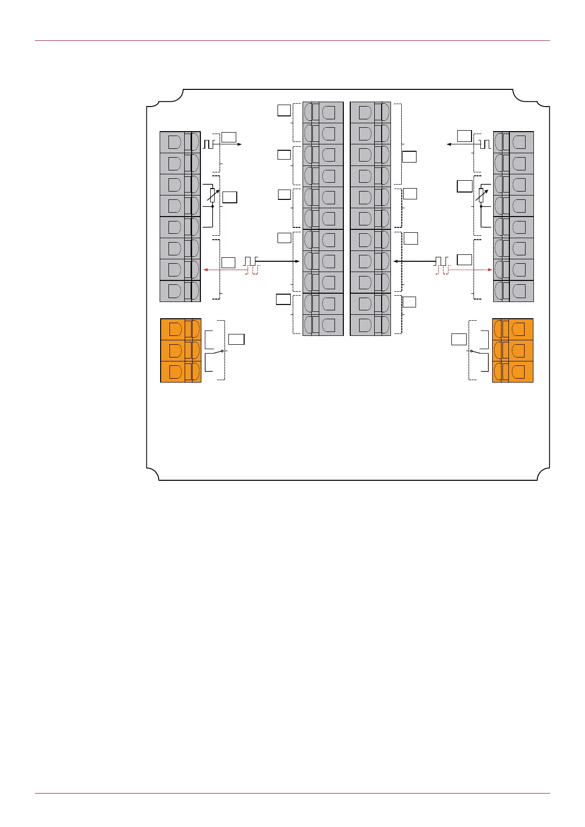
Fig.2: Termination panel electronic unit
1 Power supply (24V DC) 10 Pulse output1 (24V)
2 Modbus interface (RS485) 11 Pulse output2 (24V)
3 Serial interface (RS232) 12 Temperature inputA (Pt100)
4 Analog output1 (4-20mA) 13 Temperature inputB (Pt100)
5 Analog output2 (4-20mA) 14 Pick upA2
6 Pick upA1 15 Pick upB2
7 Pick upB1 16 Relay output1 (bypass valve/filling valve)
8 Analog output1 (0–10V) 17 Relay output2 (group error message)
9 Analog output2 (0–10V)
The Modbus connection takes place via terminals. The assignment of the terminals is shown in the wir-
ing diagram. The address of the electronic unit at the Modbus can be selected per software, see
3.19Setting Modbus address.
8
OIE 12en-GB Edition 2020-03
Operating instructions