Operating Instructions OIO 14en Edition 07/2017 35
Mounting instructions OMG 13
Maintenance
Mounting instructions OMG 13
Removing seals and bearings
Prerequisites:
□ Flowmeter removed from system
□ End connection consisting of socket screws, flanges and seals removed
□ Pick up inserts removed
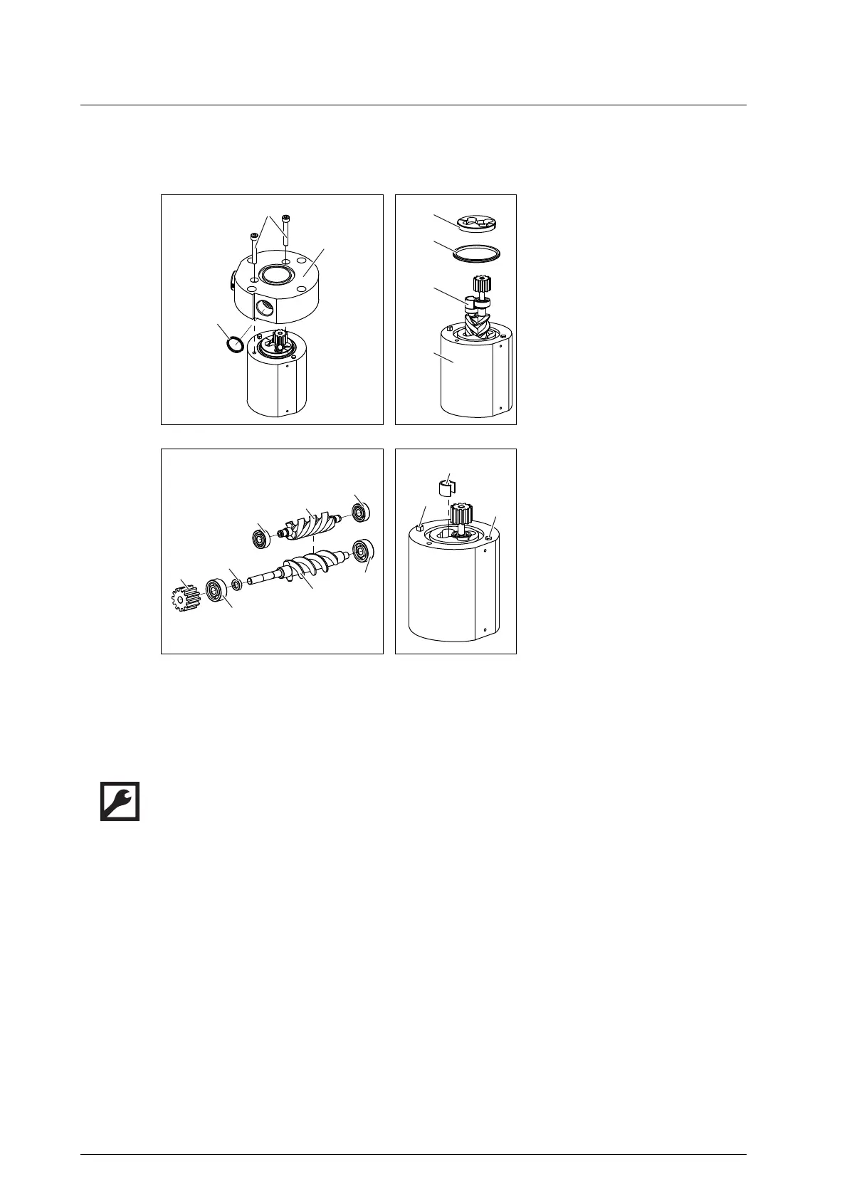
1. Remove the socket screws 915.1, take off the bearing cover 080.1.
2. Remove the O-ring 739.5** from the bearing cover, see Fig. 1, page 35.
3. Remove the spacer 062 and O-ring 739.1 , pull the screw set together with distance sleeve 039 from
the measuring housing 128. Take the combination into account to ensure subsequent assembly, see
Fig. 2, page 35.
4. Pull the pole wheel 259, ball bearing 817.1, sleeve 041 and ball bearing 817.2 from the measuring
screw large 672.1, and the ball bearings 817.3 and 817.4 from the measuring screw small 672.2, see
Fig. 3, page 35.
039
041
062
080.1
128
259
672.1
672.2
739.1
739.5**
817.1
817.2
817.3
817.4
915.1
A
**
Distance sleeve
Sleeve
Spacer
Bearing cover
Measuring housing
Pole wheel
Measuring screw large
Measuring screw small
O-ring
O-ring
Deep-groove ball bearing
Deep-groove ball bearing
Deep-groove ball bearing
Deep-groove ball bearing
Socket screws
Grooved insert pin
two units if two pick up holes
exist
Fig. 1 Fig. 2
Fig. 3 Fig. 4
039