Operating Instructions OIO 14en Edition 07/2017 41
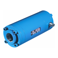
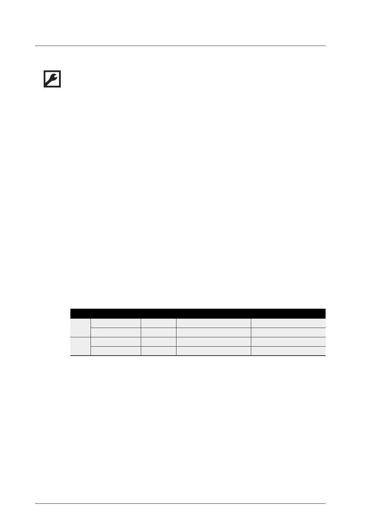
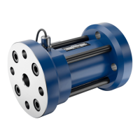
Mounting instructions OMG 52/68
Maintenance
Installing seals and bearings
1. Insert the O-rings 739.1 and 739.2 into the bearing cover 080.1 and 080.2. Insert the O-ring 739.5**
into the pick up hole.
2. Press the ball bearings 818.1 and 818.2 into the bearing cover 080.1.
Notice: Press the angular-contact ball bearings on in face-to-face arrangement, see Fig. 18, page
39. To avoid damages press the ball bearings on only over the outer ring.
3. Put spacer 054 on ball bearing 817.1.
4. Press the ball bearing 817.1 onto the measuring screw large 672.1 and the ball bearing 817.2 onto
the measuring screw small 672.2.
Notice: Press the ball bearings on only over the inner ring.
5. First screw the threaded ring 057.2, then the threaded ring 057.1 into the bearing cover using the
allen key. Allen key widths and tightening torques, see Tab. 2, page 41.
6. Press the measuring screws into the bearings in the bearing cover.
Notice: To avoid damages support the inner rings of the ball bearings.
7. Pull the lock washer 904.2 and supporting ring 064.2 onto the socket screw 915.7.
Notice: Ensure that the lock washers are positioned correctly (wedge surface to wedge surface),
see Fig. 17, page 39.
8. Mount the socket screw 915.7, with Loctite 242 applied, with mounted washer and ring onto the
measuring screw small 672.2 and tighten with torque, see Tab. 2, page 53.
9. Slide the spacer 056 onto the measuring screw large 672.1. Press the pole wheel 259 on.
10. Pull the lock washer 904.1 and supporting ring 064.1 onto the socket screw 915.6.
11. Mount the socket screw 915.6, with Loctite 242 applied, with mounted washer and ring onto t
he
measuring screw large 672.1 and tighten with torque, see Tab. 2, page 53.
12. Mount the support rings 868.2 and 868.4 and circlips 869.2 and 869.4 on the floating bearing end.
13. Place the bearing cover 080.2 onto the measuring housing 128 and tighten with torque the socket
screws 915.2.
14. Slide the bearing cover 080.1 with pre-mounted measuring unit, consisting of screw set and pole
wheel, into the measuring housing, tighten with torque the socket screws 915.1.
15. Mount the flange cover while pretensioning the oiled screws crosswise. Tightening torque see
Tab. 2, page 53.
Tab. 2 Allen key width and tightening torque for threaded ring
Size Measuring screw Pos. no. Allen key width [mm] Tightening torque [Nm]
52 large 057.1 22 90
small 057.2 19 90
68 large 057.1 32 160
small 057.2 19 55