14
Chassis
Chassis
Fuel Tank Mounting/Height Adjustment Screws
Steering Damper Adjusting Knob
Handlebar Height and Angle Adjustment
Handlebar Width Adjustment
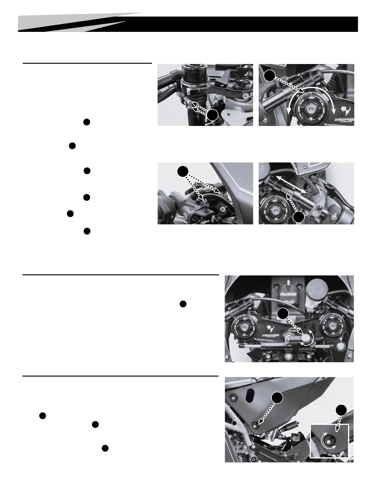
Handlebar Adjustment
The position of the handlebars is adjustable in both height and
angle. Please note that the right and the left handlebar sides
mirror each other, and neither should be at a different angle
or height.
Height and Angle Adjustment
1. Loosen the clamping screws
A
of the clip-ons on both sides.
2. Adjust the height of the handlebars by sliding them up or down on
the fork tube. Adjust the angle by rotating around the fork tube.
Use the angle marks
B
to ensure that both sides are equal.
3. Swing handlebars from lock to lock, making sure nothing touches
or rubs.
4. Tighten the clamping screws
A
of the clip-ons alternately until
the appropriate torque is attained – 10 Nm (7.4 ft-lb).
Width Adjustment (2 positions)
1. Loosen the clamping screws
C
of the clip-ons on both sides.
2. Adjust the width of the handlebars. Read the setting marks at the
edge of the window
D
. Ensure that both sides are equal.
• Check the steering for binding and kinked cables or lines.
3. Tighten the clamping screws
C
of the clip-ons alternately until
the appropriate torque is attained – 10 Nm (7.4 ft-lb).
Steering Damper Setup
Setting the steering damper’s rmness
is dependent on riding style and track
characteristics. In high-speed corners, a
higher setting may help keep the motorcycle
more stable. However, too high of a setting in
tight and twisty sections may cost valuable
agility and precision.
Adjust Damper Firmness
1. Rotate the adjusting knob
E
clockwise to the
last detectable click.
2. Adjust to the desired rmness by turning the
adjusting knob counter-clockwise.
• The Adjustment Range is 1-24 clicks
The standard is 12 clicks.
E
A
C
B
D
Seat/Tank Height Adjustment
The seat height is adjusted by moving
the complete seat/tank unit. The height
is adjusted by turning the eccentric tank
mounts
G
.
1. Loosen the bottom mount screws
F
on both
sides of the tank.
2. Using a 6 mm Allen wrench placed in the
triangular hole, turn the eccentric base
G
to
the desired seat position.
3. Temporarily tighten the left mounting screw.
4. Remove the right mounting screw, apply
blue thread lock*, reinsert and tighten to the
appropriate torque – 30 Nm (22.1 ft-lb).
5. Remove the left mounting screw, apply blue
thread lock*, reinsert and tighten to the
appropriate torque – 30 Nm (22.1 ft-lb).
* Loctite
®
243™
F
G

 Loading...