KDS-8-MNGR – Defining KDS-8-MNGR
Defining KDS-8-MNGR
Front and Back Panel
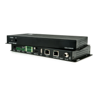
Figure 1: KDS-8-MNGR SDVoE Manager Front Panel
Lights when the device receives power.
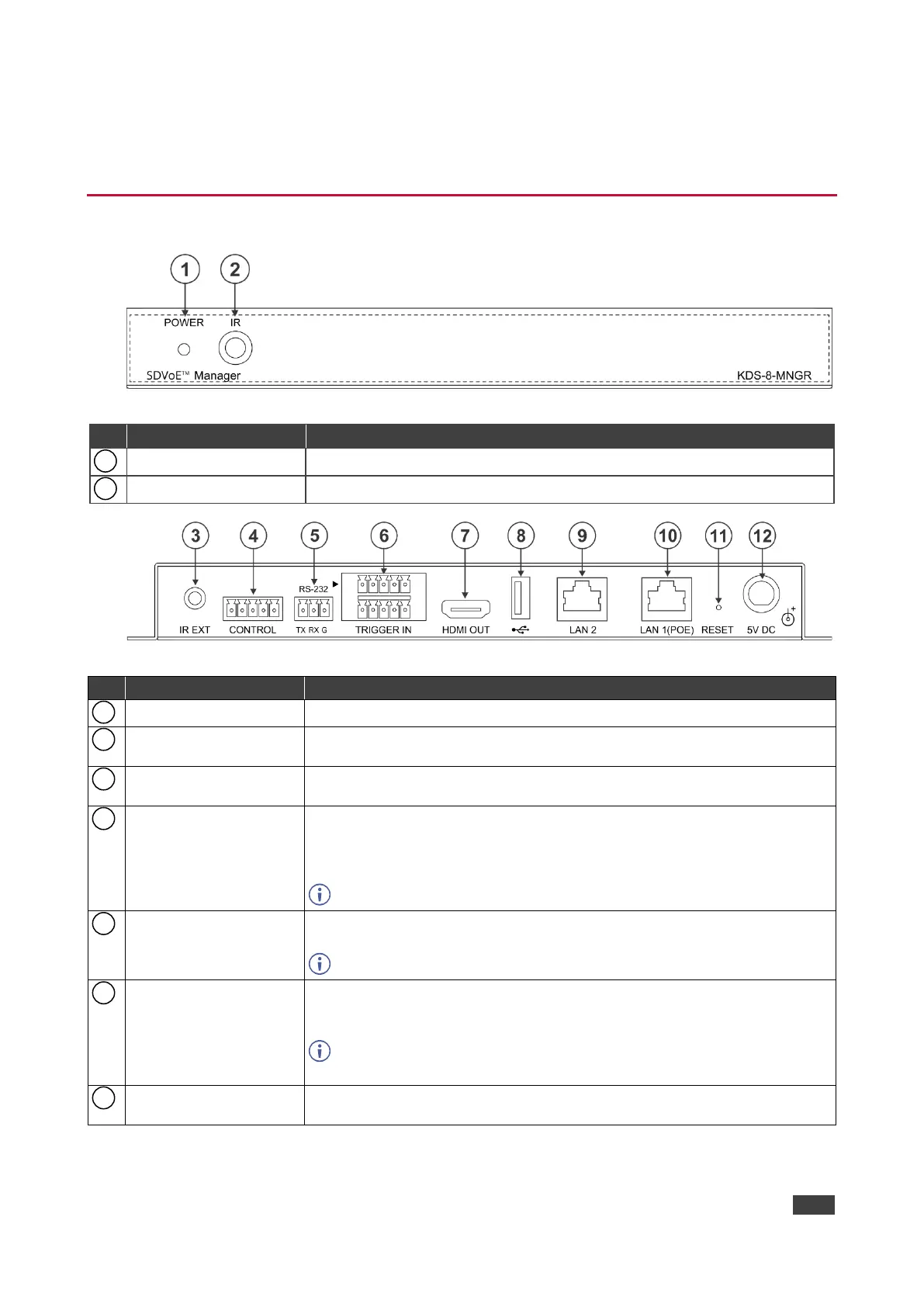
Figure 2: KDS-8-MNGR SDVoE Manager Rear Panel
CONTROL 5-pin
Terminal Block
RS-232 3-pin Terminal
Block
Connect to a PC, laptop or other serial control device with a 3-pin adapter
cable to control the unit via RS-232.
TRIGGER IN 10-pin
Terminal Block
Connect to the Trigger Control Keypad (OPTIONAL) or any device with
trigger switch functionality such as window security alarms, motion
detectors, door switches, etc. Each of the 8 trigger inputs will activate the
associated macro (1~8) when triggered.
A minimum of 5V DC is required to activate each trigger.
Connect to a standard HDMI display to view the unit current status
information and access the embedded web pages directly without a PC.
HDMI output is locked to a resolution of 1080p@60Hz.
Connect a USB mouse and keyboard to control the unit’s embedded web
pages that are displayed on the HDMI output port. Firmware update via
USB is also supported.
Specialized USB control devices, such as a touch panel, should be
connected before the unit is powered on.
Connect directly, or through a network switch, to your PC/ laptop to control
the unit via embedded web pages/Telnet.
 Loading...
