SL-280 – Defining the SL-280 Master / Room Controller Kramer Control Brain
Defining the SL-280 Master / Room
Controller Kramer Control Brain
This section defines SL-280.
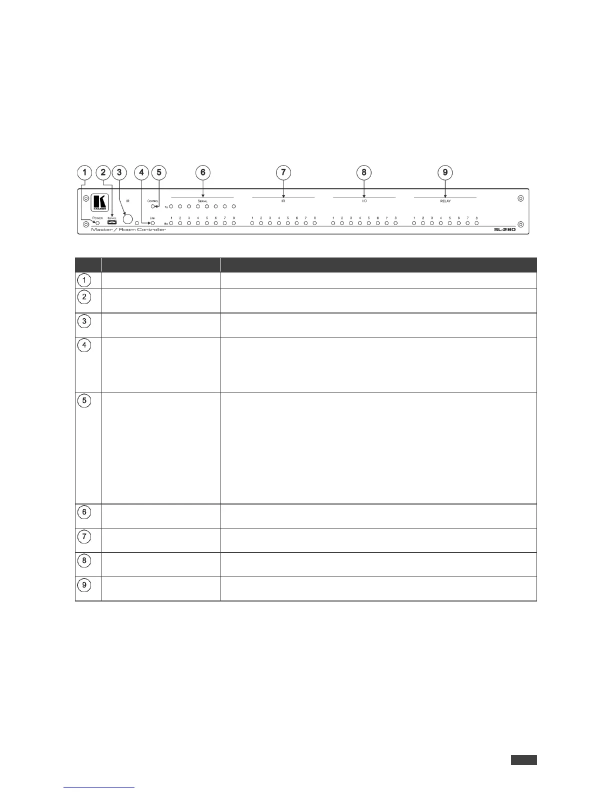
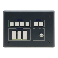
Figure 1: SL-280 Master / Room Controller Kramer Control Brain Front Panel
Lights green when powered on.
SERVICE Micro USB
Connector
Connect to a PC to send P3K commands and perform a firmware upgrade.
Detects IR signals for IR learning. Lights blue when waiting to receive a
signal.
LINK LED
Lights blue to indicate Ethernet activity:
• On – good connection
• Flashing – no connection
• Off – before first connection
CONTROL
Lights to indicate control states of the control application (brain):
• Flashing – sending data
• Green – ready and working
• White – no devices are assigned
• Blue – synchronizing
• Yellow – one or more controlled devices are disconnected
• Red – an error occurred
• Purple – Brain booting up
White Tx LEDs and blue Rx LEDs flash to indicate activity on each
channel.
Light blue to indicate IR activity on each channel (the associated LED
lights when the relevant IR port transmits data).
I/O LEDs (1–8)
Light blue to indicate I/O activity on each channel (the associated LED
lights on Digital Out HIGH, and when Digital In is triggered).
Light blue to indicate relay activity on each channel (the associated LED
lights when the relay is closed).