Connecting VW-4
You can connect up to 16 VW-4 devices to create a video-wall of 8x8, using 64 displays. In
the example below, three VW-4 devices are used to create a 6x2 video-wall.
The ID Name of the three devices in this 6x2 diagram are set by the App to 0, 1 and 2
(see Changing the Device ID Number on page 16). Each output is designated by the device
ID number and its outputs. For example, VW-4 (1) is defined as the second device in this
video-wall configuration and VW-4 (1-2) is HDMI OUT 2 on that device.
Always switch off the power to each device before connecting it to your VW-4. After
connecting your VW-4, connect its power and then switch on the power to each device.
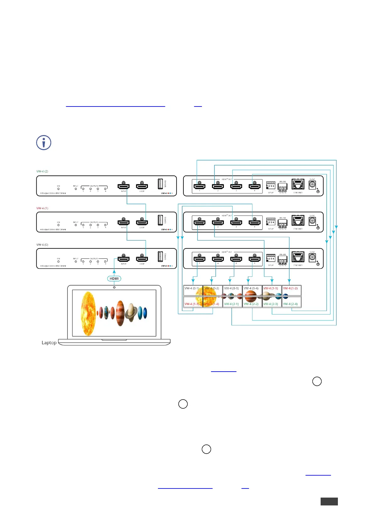
Figure 2: Connecting to the VW-4
To connect VW-4 as illustrated in the example in Figure 2:
1. Connect the HDMI source (for example, a laptop) to the HDMI INPUT connector on
the front panel of VW-4 (0).
2. Connect the LOOP HDMI connector on VW-4 (0) to the HDMI INPUT connector on
the front panel of VW-4 (1).
3. Connect the LOOP HDMI connector on VW-4 (1) to the HDMI INPUT connector on the
front panel of VW-4 (2).
4. Connect each of the HDMI OUT connectors on the three VW-4 devices to a display
(in its appropriate location on the video-wall).
5. Connect the power adapter to VW-4 and to the mains electricity (not shown in Figure 2).
6. Configure the video-wall (see Configuring VW-4 on page 10).