Servicing the Timeclock
Series 4000 Badge Timeclock User’s Guide 4-9
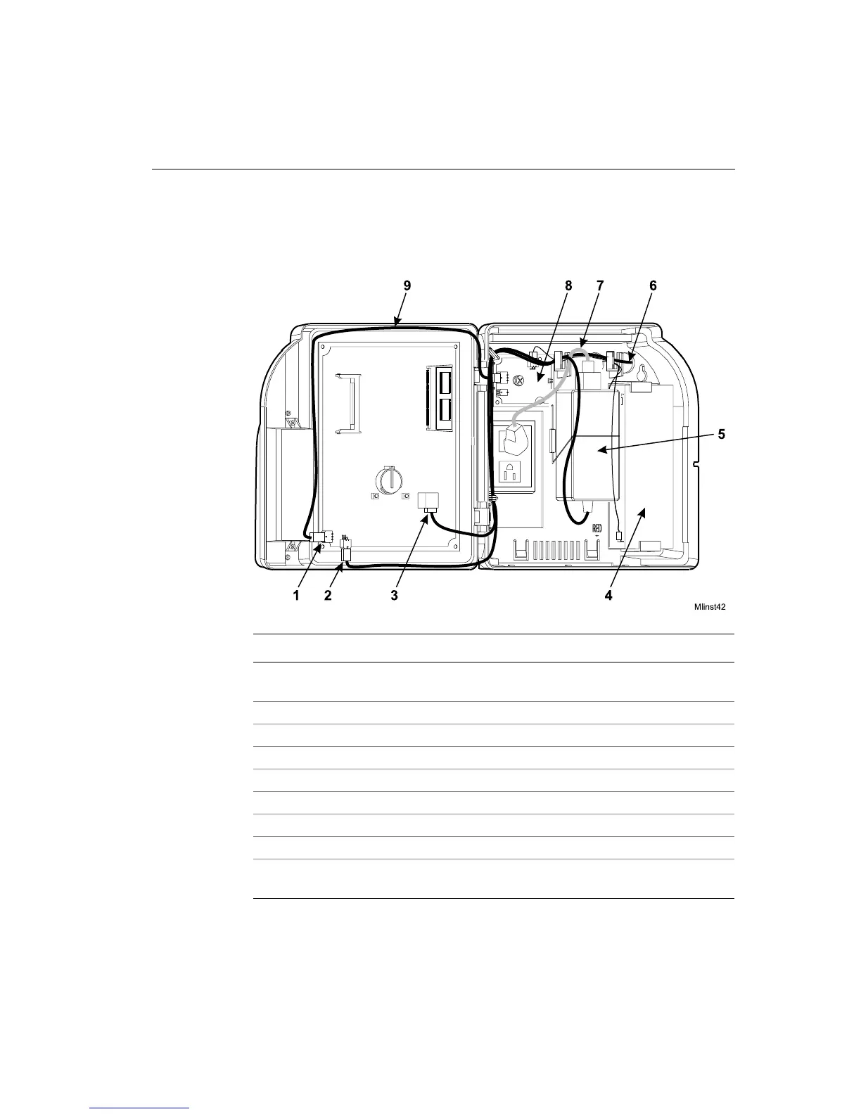
Interior of Fully-Assembled Timeclock
The following figure shows the interior of the Series 4000 timeclock:
Number Description
1 Battery charger board connection to the main board (if the backup
battery is installed)
2 Transformer connection to main board
3 Ethernet connection to main board
4 Backup battery (optional)
5 Transformer
6 Ethernet cable (shown run through the wall and into the timeclock)
7 AC power cable
8 Battery charger board (if the backup battery is installed)
9 Cables for the transformer and battery charger board (optional) routed
to their connection points on the main board (see numbers 1 and 2)


 To Next Page