4 Description of the Pump (Set)
19 of 64
KWP-Bloc
4.6 Configuration and function
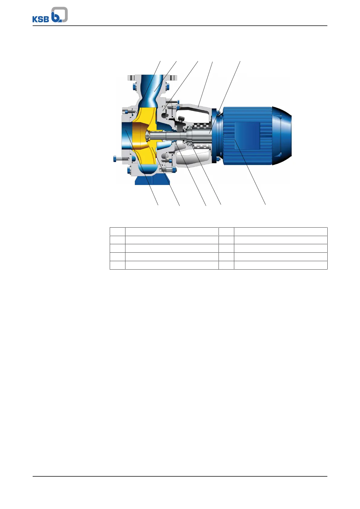
Fig.4: Sectional drawing C
2
design
1 Wear plate 2 Casing/discharge nozzle
3 Discharge cover 4 Intermediate lantern
5 Shaft 6 Casing/suction nozzle
7 Impeller 8 Shaft seal chamber
9 Bearing, pump end 10 Motor
Design The horizontal, non-self-priming, radially split volute casing pump in back pull-out
design is designed with an axial fluid inlet and a radial outlet.
The hydraulic system and the motor are firmly connected and form a close-coupled
unit. Impeller (7) and motor (10) are arranged on a common shaft (5).
Function The steadily rotating impeller (7) of the centrifugal pump transfers mechanical
energy to the fluid passing through.
The fluid enters the pump axially via a suction nozzle (6) and is accelerated outward
in a cylindrical flow by the rotating impeller (7). The flow profile of the pump casing
converts the kinetic energy of the fluid into pressure energy. The fluid leaves the
pump via the discharge nozzle (2).
The casing is fitted with a replaceable wear plate (1). The diagonal clearance gap
prevents frequent deviation of the flow in the clearance gap heading in the direction
of the suction nozzle. This ensures a longer service life if solids-laden fluids are
handled.
The casing is closed by a discharge cover (3). The shaft (5) enters the casing via this
discharge cover. A shaft seal (8) provides reliable sealing towards the atmosphere.
The shaft is supported by oil-lubricated rolling element bearings (9). The motor (10) is
connected to the casing via an intermediate lantern (4).
Sealing The pump is sealed with a shaft seal.