5 Installation at Site
24 of 64
KWP-Bloc
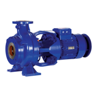
5.3.2 Permissible forces and moments at the pump nozzles
[+]
F
y
F
z
F
x
F
x
F
z
F
y
F
x
F
z
F
y
M
y
M
z
M
x
Forces and moments at the pump nozzles
The resulting permissible forces have
been determined according to:
The data on forces and moments apply to static piping loads only. If the limits are
exceeded, they must be checked and verified.
If a computerised strength analysis is required, values are available on request only.
The values are only applicable if the pump is installed on a completely grouted
baseplate and bolted to a rigid and level foundation.
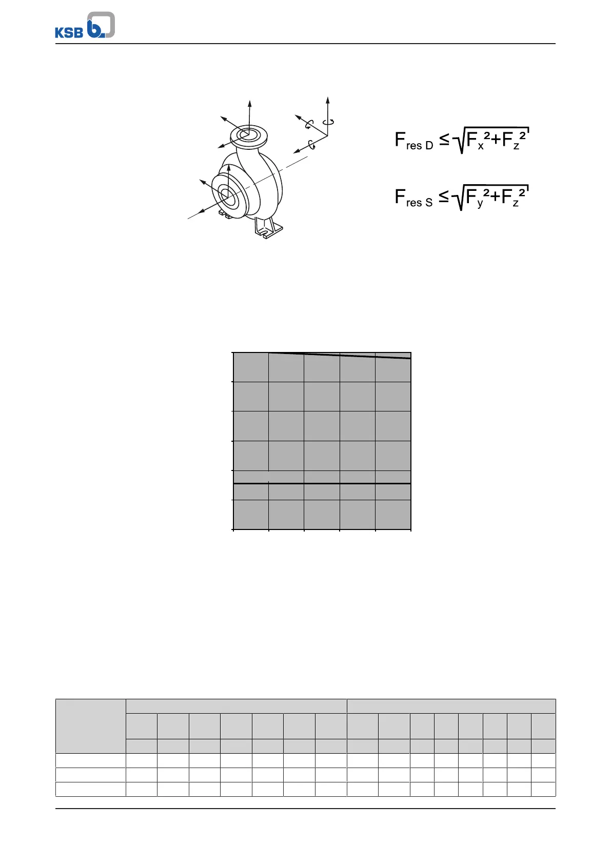
Correction coefficients depending on material and temperature (see diagram below).
DDDD
GNNG, GDNG
0,4
0,5
0,6
0,7
0,8
0,9
1
0 20 40 60 80 100
k = f(T)
T [°C]
Fig.6: Temperature correction diagram
Calculation of forces and moments for T > 20°C
Reduction formula:
Permissible force/moment = k (T) x force/moment from table
Example:
▪ Material = DDDD
▪ T = 100°C
▪ k = 0.98
Table11: Permissible forces (F) and moments (M) at the pump nozzles
Size Suction nozzle Discharge nozzle
F
x
F
y
F
z
F
res
M
x
M
y
M
z
F
x
F
yTens+
F
yCom
pr-
F
z
F
res
M
x
M
y
M
z
[N] [N] [N] [N] [Nm] [Nm] [Nm] [N] [N] [N] [N] [N] [Nm] [Nm] [Nm]
065-040-0250 3145 2065 2515 3235 2065 1525 1080 1527 990 1975 1255 1975 990 810 540
080-040-0315 3860 2515 3055 3950 2605 1975 1345 1527 990 1975 1255 1975 990 810 540
065-050-0200 3145 2065 2515 3235 2065 1525 1080 1527 990 1975 1255 1975 1255 990 630