5 Installation at Site
23 of 64
KWP-Bloc
NOTE
Installing check and shut-off elements in the system is recommended, depending on
the type of plant and pump. However, such elements must not obstruct proper
drainage or hinder disassembly of the pump.
ü The suction lift line has been laid with a rising slope, the suction head line with a
downward slope towards the pump.
ü A flow stabilisation section having a length equivalent to at least twice the
diameter of the suction flange has been provided upstream of the suction flange.
ü The nominal diameters of the pipelines are equal to or greater than the nominal
diameters of the pump nozzles.
ü The pipelines have been anchored in close proximity to the pump and connected
without transmitting any stresses or strains.
1. Thoroughly clean, flush and blow through all vessels, pipelines and connections
(especially of new installations).
2. Before installing the pump in the piping, remove the flange covers on the
suction and discharge nozzles of the pump.
CAUTION
Welding beads, scale and other impurities in the piping
Damage to the pump!
▷ Remove any impurities from the piping.
▷ If necessary, install a filter.
▷ Observe the information in (ðSection7.2.2.1,Page40) .
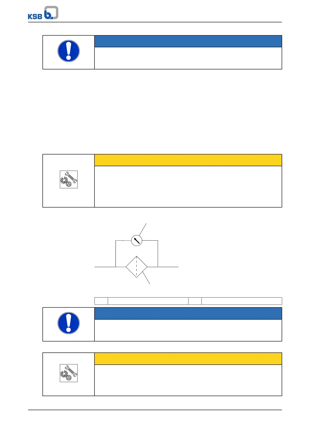
3. If required, install a filter in the piping (see drawing: Filter in the piping).
Fig.5: Filter in the piping
1 Differential pressure gauge 2 Filter
NOTE
Use a filter made of corrosion-resistant material.
Use a filter with a filter area three times the cross-section of the piping.
Conical filters have proved suitable.
4. Connect the pump nozzles to the piping.
CAUTION
Aggressive flushing liquid and pickling agent
Damage to the pump!
▷ Match the cleaning operation mode and duration of flushing and pickling to
the casing materials and seal materials used.