5 Installation at Site
21 of 64
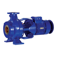
KWP-Bloc
5 Installation at Site
5.1 Checks to be carried out prior to installation
Place of installation
WARNING
Installation on mounting surface which is unsecured and cannot support the load
Personal injury and damage to property!
▷ Use a concrete of compressive strength class C12/15 which meets the
requirements of exposure class XC1 to EN206-1.
▷ The mounting surface must be set, flat, and level.
▷ Observe the weights indicated.
1. Check the structural requirements.
All structural work required must have been prepared in accordance with the
dimensions stated in the outline drawing/general arrangement drawing.
5.2 Installing the pump set
DANGER
Static charging due to insufficient potential equalisation
Explosion hazard!
▷ Make sure that the connection between pump and baseplate is electrically
conductive.
Installing the pump set in a horizontal position
No special foundation is required for installation. An even slab of concrete is
sufficient as an installation surface.
On pumps supplied with a mounting plate, the mounting plate can be used as a
template for drilling.
The mounting plate and the foundation rails must not be set in concrete.
ü The installation surface has the required strength and characteristics.
1. Position the pump set on the anchoring holes and align it with the help of a
spirit level (on the discharge nozzle).
2. Compensate any differences in height until the discharge nozzle is in a
horizontal position.
3. Fasten the pump set.
The screws/bolts are not included in the scope of supply.
Size Fasteners
Foundation bolts Expanding anchor bolts
065-040-0250 M16×200 MU -
065-050-0200 M16×200 MU -
065-050-0201 M16×200 MU -
080-065-0200 M16×200 MU -
080-065-0201 M16×200 MU -
080-040-0315 M16×200 MU F1/18-60, Ø 18×160
080-065-0313 M16×200 MU F1/18-60, Ø 18×160
080-065-0315 M16×200 MU F1/18-60, Ø 18×160
100-080-0250 M16×200 MU F1/18-60, Ø 18×160
100-080-0251 M16×200 MU F1/18-60, Ø 18×160
100-080-0311 M16×200 MU F1/18-60, Ø 18×160