3. Remove the CPU module from slot 1.
4.
Rotate the CPU module 180° and connect it to slot 2.
5. Rotate the control panel 180° and mount to PumpDrive.
5.4.3.8 Mounting the housing cover
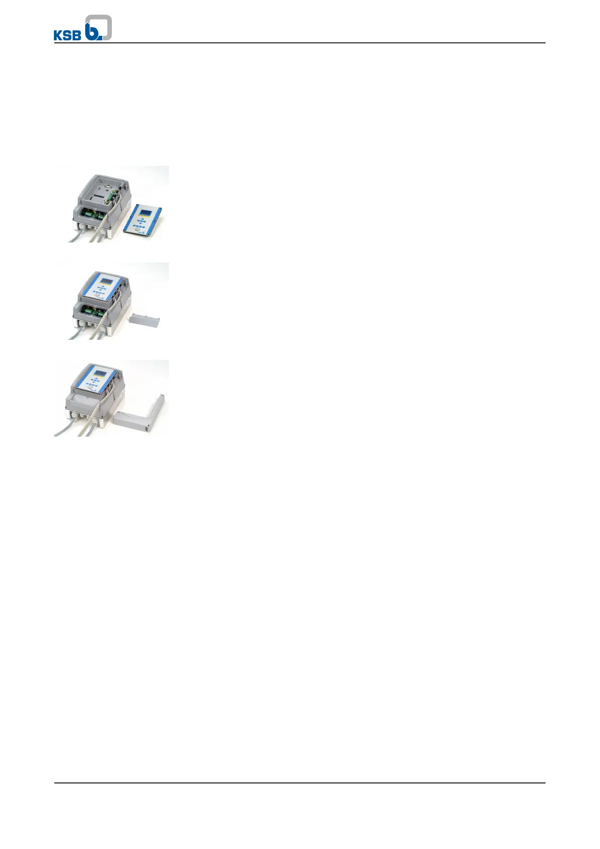
1. Position the control panel or blanking plate.
2.
Tighten the cross-head screws of the control panel or blanking plate by
applying 0.5 Nm of torque to ensure compliance with IP 55 enclosure protection
requirements.
1. Position the V-shaped cover while ensuring that the gasket is seated correctly.
2.
Tighten the cross-head screws of the cover by applying 1.2 Nm of torque to
ensure compliance with IP 55 enclosure protection requirements.
1. Position the L-shaped covers while ensuring that the gaskets are seated
correctly.
2.
Tighten the cross-head screws of the cover.
Control panel/blanking
plate
V-shaped cover
L-shaped cover
5 Installation at Site
36 of 162
PumpDrive