recognition function and the PI controller via parameters
3-9-1-6
and
3-9-1-1
. If the
system has been commissioned/started up before, restoring the factory settings will
cause all parameter settings made so far to be deleted if they have not been backed
up using the service software.
In multiple pump configurations, the PumpDrives must be reset to the factory
settings using the active master control panel.
7.4 Digital and analog inputs/Digital and analog outputs
In multiple pump configurations, the digital inputs, relay outputs, and analog
outputs must be parameterised individually for each PumpDrive.
7.4.1 Digital inputs
PumpDrive is equipped with six digital inputs (24 V process level). Inputs 1 and 6 are
assigned a fixed function:
▪ Digital input 1: Start/stop command for single-pump operation, enable in
multiple pump configurations
▪ Digital input 2: Start/stop command in multiple pump configurations (must be set
manually)
Digital input 6: Changeover to multiple pump configuration
The functions of inputs 2 to 5 are user-defined:
Table 101: Parameters for the digital inputs
Parameter Description Possible settings Factory setting
3-7-1-2
Function of Digital IN 2 Selection list I (⇨ Section 10.1 Page 129) 7
3-7-1-3
Function of Digital IN 3 10
3-7-1-4
Function of Digital IN 4 9
3-7-1-5
Function of Digital IN 5 2
PumpDrive functions of digital inputs:
▪ Fixed frequencies via digital inputs (⇨ Section 7.2.5 Page 90)
▪ Open-loop control mode via digital potentiometer function (⇨ Section 7.1.1.3.4
Page 53)
▪ Selecting the output variable for the analog output (⇨ Section 7.4.4 Page 96)
7.4.2 Relay output
Operating status information can be queried at the two volt-free contacts (NO relays)
of PumpDrive (the corresponding warnings have to be activated beforehand
(⇨ Section 7.2.3 Page 82) :
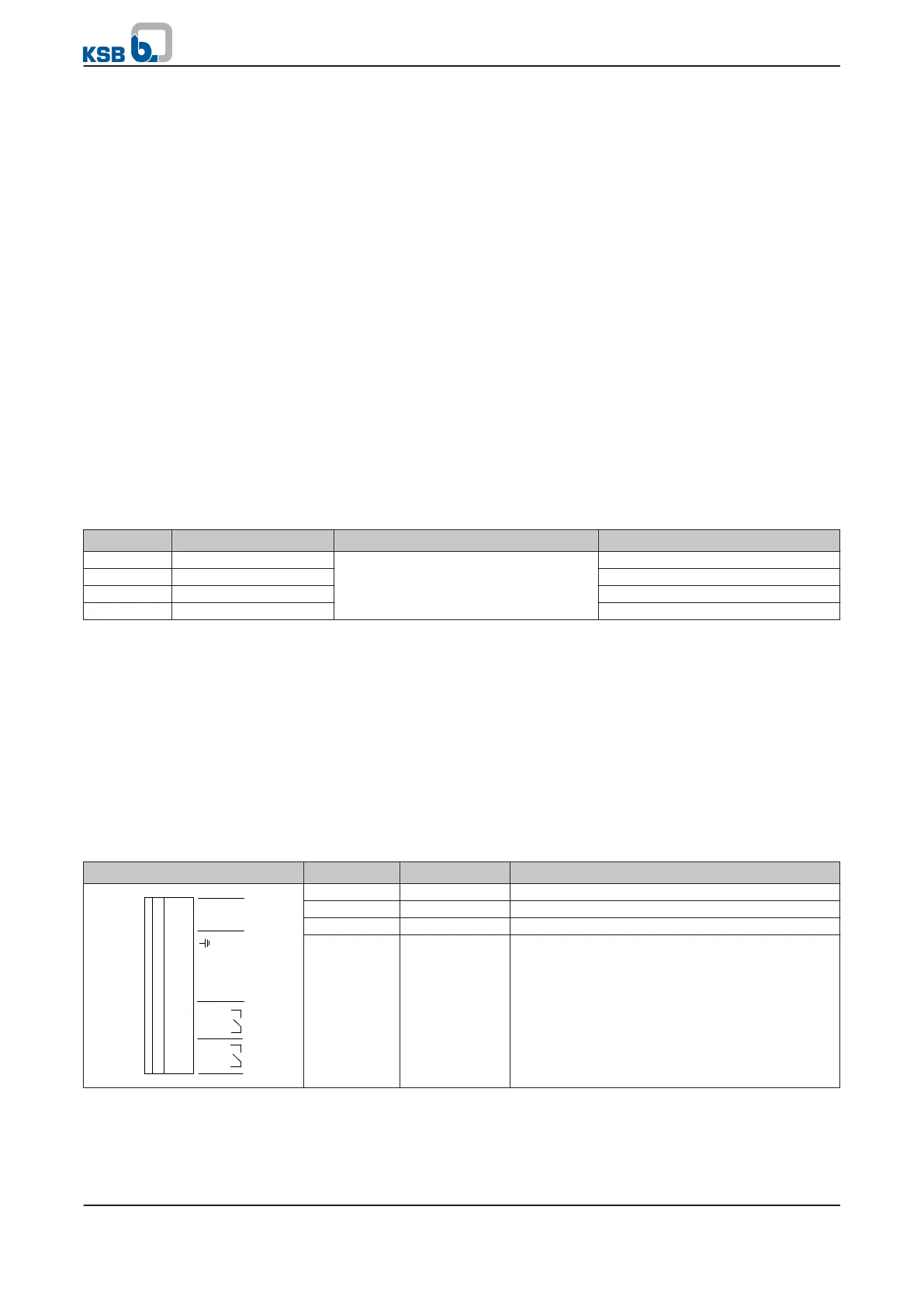
Table 102: Assignment of control terminals, P7 terminal strip
Terminal strip Terminal Signal Description
AIN1
AGND P7
GND
AIN2
NO2
COM2
NO1
COM1
+24V
10
9
8
7
6
5
4
3
2
1
4 NO2 NO contact, "NO" No. 2 (250 V AC, 1 A)
3 COM2 NO contact, "NO" No. 2 (250 V AC, 1 A)
2 NO1 NO contact, "NO" No. 1 (250 V AC, 1 A)
1 COM1 NO contact, "COM" No. 1 (250 V AC, 1 A)
7 Commissioning/shutdown
94 of 162
PumpDrive