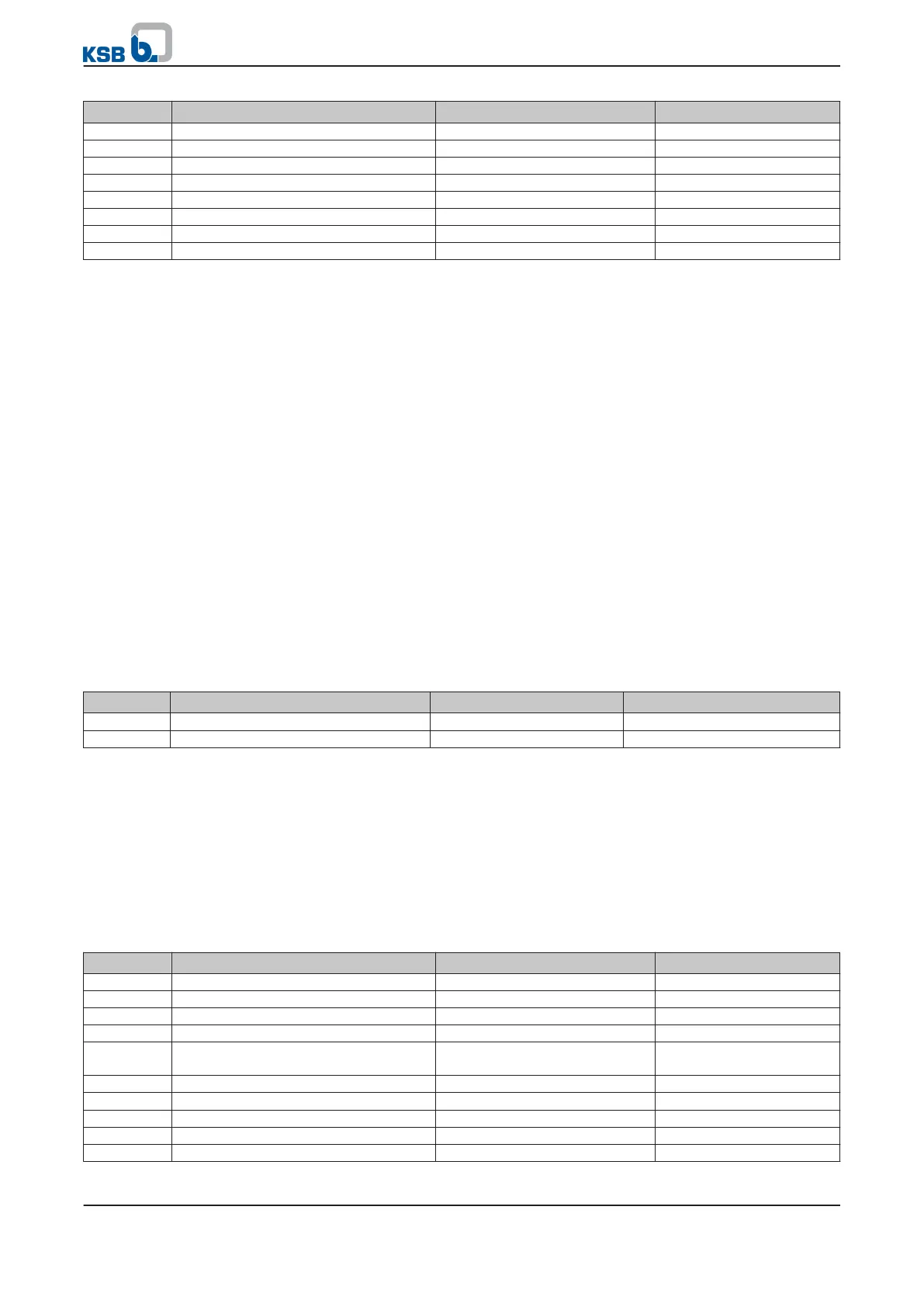
Parameter Description Settings Factory setting
3-5-1-2
Minimum setpoint 0 0
3-5-1-3
Maximum setpoint 100 100
3-5-2-1
Configurable setpoint 83,33 0
3-5-4-1
Setpoint source 1 None Analog IN 1
3-5-4-2
Setpoint source 2 Configurable Setpoint Configurable Setpoint
3-5-4-3
Setpoint source 3 None Remote Setpoint
3-9-1-1
PI mode Disabled Disabled
3-9-1-6
PI Auto Deactivated Activated
1. Change parameter
3-9-1-6
.
2. Change parameter
3-9-1-1
.
⇨ The value displayed for parameter
1-3-1-3
Setpoint is 83.33 %.
Standard control panel
The setpoint can also be specified using the standard control panel (⇨ Section 6.1.5
Page 39) .
7.1.1.3.3 Open-loop control mode using field bus
If the setpoint is specified using a field bus (e.g. LON, Profibus), the Setpoint Source 3
parameter
(3-5-4-3)
has already been set to Remote Setpoint for this purpose.
However, the bus module needs to be enabled after installation by using the Field
Bus Enable parameter
(3-2-1-5)
, so that the setpoint can be read. The setpoint
specifications have to be taken from the relevant product literature of the bus
modules, but are matched with the basic settings of PumpDrive.
7.1.1.3.4 Open-loop control mode using a digital potentiometer (key function)
This function can be activated for single-pump operation at any time as soon as the
parameterised digital inputs are connected. This function can be used to adjust the
speed via external keys or pulses. Two digital inputs are used for this purpose.
Table 52: Parameters for open-loop control mode via digital potentiometer function
Parameter Description Settings Input
3-7-1-4
Function of Digital IN 4 Preset Setpoint + Digital input 4 (terminal P4: 17)
3-7-1-3
Function Digital IN 3 Preset Setpoint - Digital input 3 (terminal P4: 16)
The Configurable Setpoint Increment parameter
(3-5-2-2)
defines the percentage by
which the setpoint is to be increased or decreased per pulse at the digital input.
Speed adjustment will be effected within the parameterised frequency range.
If the set speed is not changed for 10 minutes, the value will be saved and used as
the base value when the system is started again.
If the digital inputs are activated for an extended period of time (max. pulse duration
> 1 s), the setpoint will move continuously to the upper or lower setpoint range.
A digital potentiometer is to be realised via digital inputs 3 and 4. Digital inputs 3
and 4 decrease and increase the setpoint, respectively.
Table 53: Sample parameterisation of digital potentiometer function
Parameter Description Settings Factory setting
3-2-2-1
Setpoint unit % %
3-2-2-3
Pressure unit % %
3-5-1-2
Minimum setpoint 0 0
3-5-1-3
Maximum setpoint 100 100
3-5-2-2
In/decrement for adjusting the setpoint
frequency
0,1 0,1
3-5-4-1
Setpoint source 1 None Analog IN 1
3-5-4-2
Setpoint source 2 None Configurable Setpoint
3-5-4-3
Setpoint source 3 None Remote Setpoint
3-7-1-3
Function of Digital IN 3 Preset Setpoint - Preset Setpoint -
3-7-1-4
Function of Digital IN 4 Preset Setpoint + Preset Setpoint +
Example
7 Commissioning/shutdown
PumpDrive
53 of 162