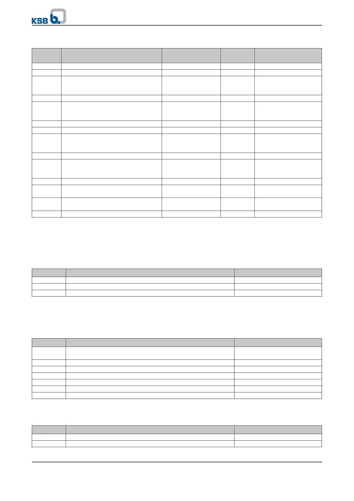
Table 61: Start and stop parameters in multiple pump configurations
Paramete
r
Description Possible settings Reference
to
Factory default
3-6-4-1
High load at low motor frequency 0..100 [%]
3-3-2-1
60 %
3-6-4-2
High load at high motor frequency 0..100 [%]
3-3-2-1
90 %
3-6-4-3
High load profile Linear
Square
Cubic
- Linear
3-6-4-4
High load time delay 0 - 30 [s] - 5 s
3-6-4-5
Function for high load warning No Function
Warning
Stop and Trip
- No Function
3-6-4-6
Low load at low motor frequency 0..100 [%]
3-3-2-1
30 %
3-6-4-7
Low load at high motor frequency 0..100 [%]
3-3-2-1
60 %
3-6-4-8
Low load profile Linear
Square
Cubic
- Linear
3-6-4-9
Low load time delay 0..30 [s] - 10 s
3-6-4-10
Function for low load warning No Function
Warning
Stop and Trip
- No Function
3-3-21
Nominal motor power 0,55..45 [kW] - Depending on the size
3-6-1-2
Lower limit for motor frequency 0 [%] to Frequency
High
(3-6-1-3)
3-11-4-1
50 %
3-6-1-3
Upper limit for motor frequency Frequency Low
(3-6-1-2)
to 100 [%]
3-11-4-1
100 %
3-11-4-1
Maximum output frequency 1 - 70 [Hz] - 50 Hz
7.1.3.2 Configuration example
The following parameterisation example applies to a multiple pump configuration
with a main pump, an auxiliary main pump and a slave pump. The PumpDrives used
are equipped as follows:
Table 62: Multiple pump configuration example
PumpDrive Role Control panel
1 Main pump with active master control panel Advanced
2 Auxiliary main pump with auxiliary master control panel Advanced
3 Slave pump Standard
The parameter settings of the individual PumpDrives have to be made/checked as
follows:
Parameterise PumpDrive1 with active master control panel
Table 63: Configuration example for multiple pump operation: PumpDrive 1
Parameter Description Value
3-1-7-4
Time value for identifying the control panel as the active master
control panel
1.0 s
3-2-1-1
Role in multiple pump configuration Auxiliary main pump
3-2-1-2
PumpDrive ID 1
3-7-1-2
Function of digital input 2 System start
3-10-1-3
Time value for identifying the control panel as the main pump 2.5 s
3-12-5-1
Maximum number of pumps running simultaneously 2
3-12-5-5
Pump changeover Enabled
Parameterise PumpDrive 3 using the active master control panel of PumpDrive 1:
Table 64: Configuration example for multiple pump operation: PumpDrive 3
Parameter Description Value
3-1-1-4
Selection of a PumpDrive from the multiple pump configuration Pump 3
3-2-1-1
Role in multiple pump configuration Standard slave
7 Commissioning/shutdown
PumpDrive
67 of 162