GN
D
D
I
6
D
I
5
D
I4
D
I
3
DI2
D
I1
+24
V
A
G
ND
AN-OUT
G
ND
D
I6
DI
5
DI4
D
I3
DI2
DI1
+
24V
AGND
AN
-OU
T
G
N
D
D
I6
DI5
DI4
DI3
D
I
2
DI1
+
2
4
V
AGND
A
N
-O
U
T
109876543211098765432110987654321
1918171615141312112019181716151413121120191817161514131211 20
SB
1
_GND
SB1+
S
B
1-
SB1_GND
SB1
+
SB1-
S
B1
Z-
SB1Z+
SlaveMaster
1
AG
N
D
A
IN
1
GND
A
I
N
2
+24V
N
O
2
C
O
M
2
N
O1
C
O
M1
10931 2 4 5 6 7 8
AGND
AIN1
GND
AIN2
+24
V
N
O2
COM
2
NO1
COM1
10931 2 4 5 6 7 8
AGND
AIN1
G
N
D
AIN2
+24
V
NO2
COM2
N
O
1
C
O
M
1
10931 2 4 5 6 7 8
Sensor
4...20mA
1
500Ω
Aux-Master
AG
N
D
A
IN
1
G
N
D
AIN
2
+24V
N
O2
C
OM2
N
O1
CO
M1
10931 2 4 5 6 7 8
S
B
1
_
GN
D
SB1
+
SB1-
SB1_GND
SB
1
+
SB
1-
S
B
1Z-
SB1
Z
+
SB
1
_G
N
D
S
B1
+
SB1-
SB1_GND
SB
1+
S
B
1-
SB1Z-
SB
1
Z+
Sensor
4...20mA
AGND
A
IN
1
GN
D
AIN2
+2
4
V
NO2
COM2
NO
1
C
O
M1
10931 2 4 5 6 7 8
Sensor
4...20mA
A
GN
D
A
IN
1
GND
AIN
2
+24V
NO2
COM2
NO
1
COM1
10931 2 4 5 6 7 8
P4 P4
P4
P4 P4 P4
P7 P7 P7
P7
P7
P7
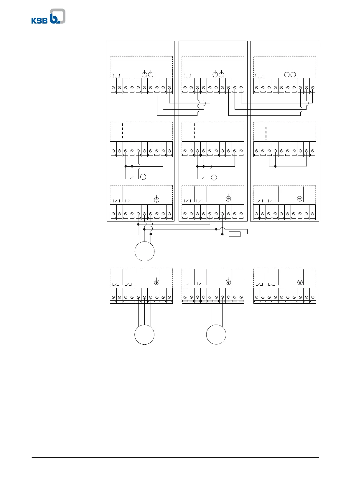
Fig. 40: KSB local bus wiring for master/auxiliary master/slave mode (1 main pump, 1
auxiliary pump, 1 slave pump)
1. The KSB local bus in the first and last PumpDrive must be terminated via a
resistor. This is implemented by means of a wire jumper between terminals 1
and 2 on terminal strip P4. If a graphical control panel is used on the first or last
PumpDrive, the wire jumper is not required.
2. At the centre PumpDrives, the DIP switches on the rear must, if a graphical
control panel is used, be set to OFF to deactivate the terminating resistor of the
KSB local bus.
Master/AUX master/slave
mode
(1 main pump, 1 auxiliary
pump, 1 slave pump)
7 Commissioning/shutdown
70 of 162
PumpDrive