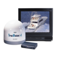
Below-decks Cable Lengths
The major considerations in locating the below-decks equipment
are accessibility and cable lengths between units. Lengths of these
cables are as follows:
Cable (Function) Length
Data Cable (Switchplate to Antenna Unit) 50 ft (15 m)
RF Cable (Antenna to IRD) 50 ft (15 m)
Power Cable (Power to Antenna Unit) 50 ft (15 m)
IRD Ground Wire 50 ft (15 m)
2.1 Choosing the Best Location and
Getting the Best Reception
There are several factors to consider when choosing the
respective locations of the TracVision 4 antenna unit.
• The ideal antenna site has a clear view of the
horizon/satellite all around.
• Tracking errors will be reduced if the antenna
forward arrow is aligned as closely as possible
with the vessel’s centerline.
• Place the Antenna Unit as close to the intersection
of the vessel’s fore-and-aft centerline and midships.
• Keep the antenna out of line with nearby radars,
as their energy levels may overload the antenna’s
front-end circuits. If necessary, position the
Antenna Unit so it is at least four feet (1.3 meters)
above or below the level of the radar.
• Make sure that the mounting surface is rigid so
that it cannot flex when the vessel vibrates. If
necessary, add a strength member to the mounting
site to stiffen it.
2.2 Installing the Antenna Unit
Specifics of installation will vary with vessel design but the
following procedures are applicable in most situations and will
result in a secure and effective installation.
2-2
TracVision 4 Installation and Technical Manual
The radome exterior is treated
with a special finish selected for
compatibility with the dome material
and transparency to the satellite
signals. Application of additional
paints or finishes WILL degrade
performance, potentially beyond
acceptable limits.
The Antenna Unit should not be too
high off the water (a height above
the waterline no more than half the
vessel length).
Table 2-2
Lengths of Provided
Below-decks Cables

 Loading...