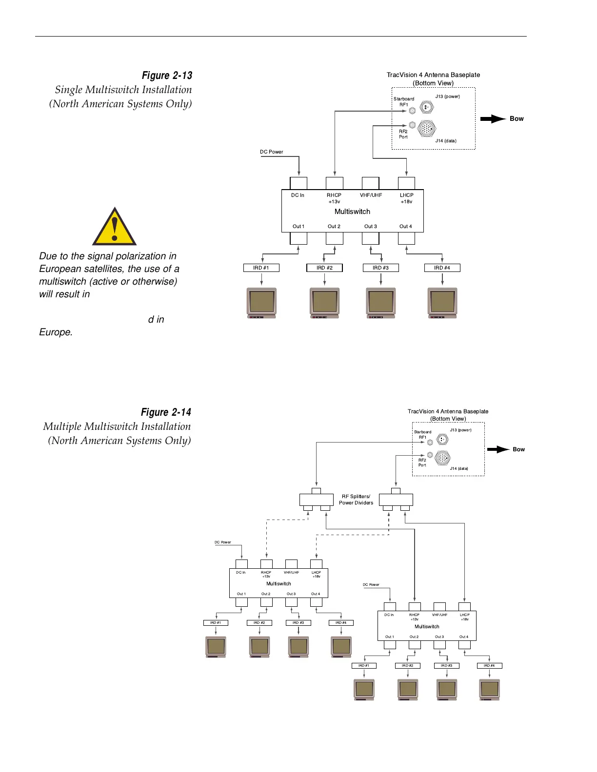
Multiple Multiswitch Installation
If there is a need for more than four IRDs, it is possible to
carry out a multiple multiswitch installation, as illustrated in
Figure 2-14.
2-12
TracVision 4 Installation and Technical Manual
Starboard
RF1
RF2
Port
J14 (data)
J13 (power)
TracVision 4 Antenna Baseplate
(Bottom View)
Multiswitch
DC In RHCP
+13v
VHF/UHF LHCP
+18v
Out 1 Out 2 Out 3 Out 4
DC Power
IRD #1 IRD #2 IRD #4IRD #3
Multiswitch
DC In RHCP
+13v
VHF/UHF LHCP
+18v
Out 1 Out 2 Out 3 Out 4
DC Power
IRD #1 IRD #2 IRD #4IRD #3
RF Splitters/
Power Dividers
Bow
Figure 2-14
Multiple Multiswitch Installation
(North American Systems Only)
Starboard
RF1
RF2
Port
J14 (data)
J13 (power)
TracVision 4 Antenna Baseplate
(Bottom View)
Multiswitch
DC In RHCP
+13v
VHF/UHF LHCP
+18v
Out 1 Out 2 Out 3 Out 4
DC Power
IRD #1 IRD #2 IRD #4IRD #3
Bow
Figure 2-13
Single Multiswitch Installation
(North American Systems Only)
Due to the signal polarization in
European satellites, the use of a
multiswitch (active or otherwise)
will result in a loss of signal and
less than optimal operation with
TracVision 4 systems used in
Europe.

 Loading...


