4.4.1 CPU Board
1. Remove the seven Molex connectors from the CPU.
2. Remove eleven #6-32 x
3
⁄
8" machine screws,
lockwashers and flat washers from the PCB.
3. Remove the assembly from the main support.
4. Installation of the replacement assembly is the
reverse of this. Reinstall all Molex connectors
removed in Step 1.
5. Calibrate the Gyro and LNB as described in
Section 4.5.
6. Reinstall your preferred satellites as instructed in
Section 2.5, “Selecting the Active Satellite.”
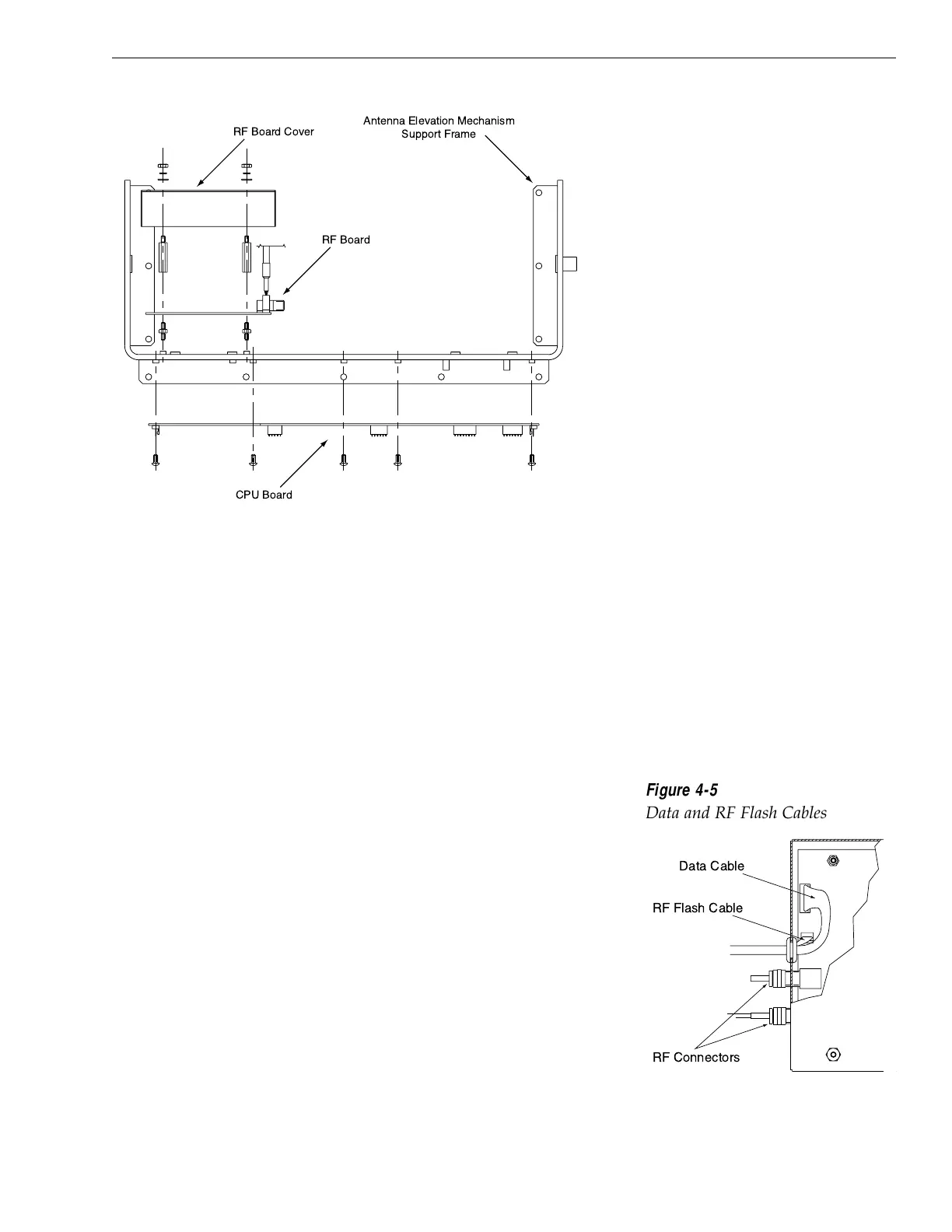
4.4.2 RF Detector
The RF Detector receives operating voltages from both the CPU
board and the IRD (via the RF cable). Ensure that all power
(including the IRD) is turned off before proceeding.
1. Use a
5
⁄
16" socket to remove the four nuts and
washers securing the RF Board cover. Set the
hardware and cover aside.
2. Cut the tie-wrap securing the Data and RF Flash
cables (pictured in Figure 4-5) to the RF Board.
4-5
Maintenance
54-0150 Rev. E
Figure 4-4
PCB Mounting (Top View)

 Loading...


