3. Unplug the Data and RF Flash cables from the
RF Board.
4. Observe which RF cable is attached to the top RF
connector. If the top RF cable is not already
marked with yellow tape, add a piece of tape or
some identifying mark so that the RF cables can be
plugged into the proper RF connectors on the new
RF Board.
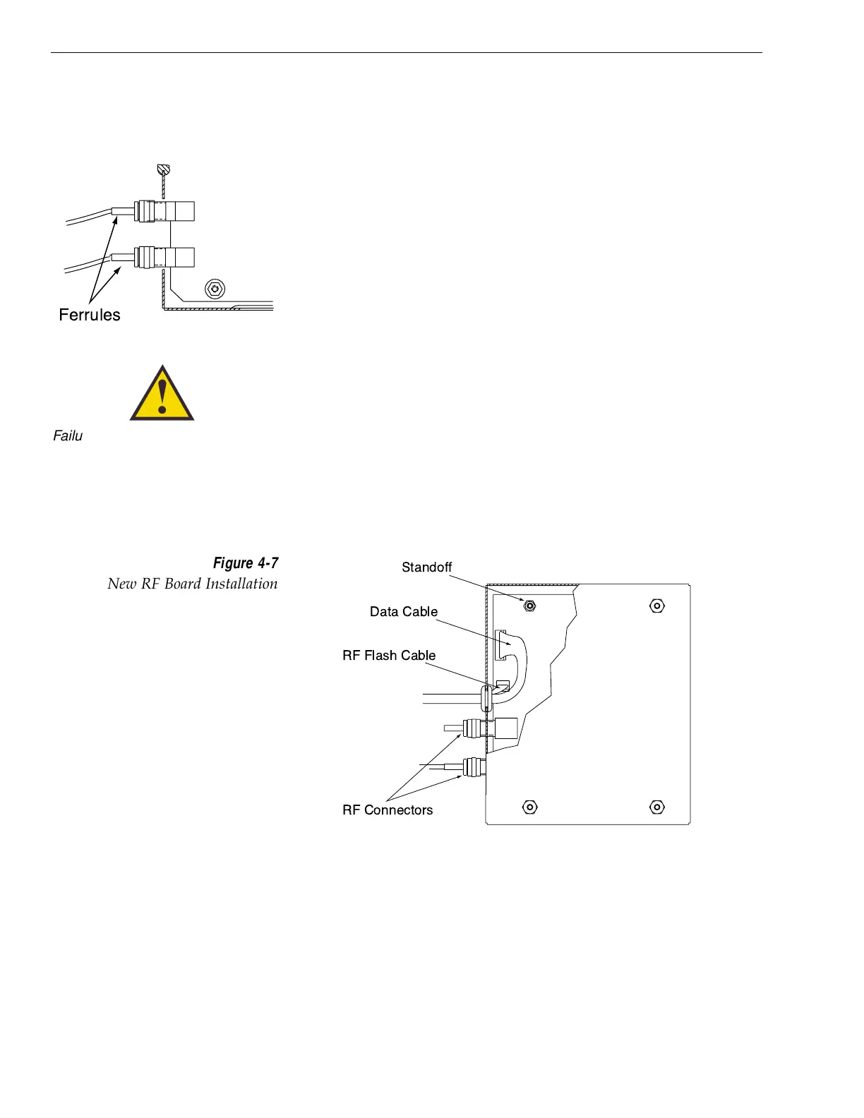
5. Remove the two RF cables from the RF connectors
with a
7
⁄16" wrench. Hold the RF connector ferrule
while loosening the connectors to avoid excess
stress on or twisting of the cables. Refer to Figure
4-6.
6. Remove the four 1
1
⁄
16" standoffs with a
1
⁄
4" nut
driver/socket and set aside.
7. Remove the RF Board and discard.
8. Install the new RF Board, making certain to align
the Board so that the RF connectors are facing to
the inside. Figure 4-7 illustrates the alignment of
the new RF Board, the standoffs, cables, and cover.
9. Apply a drop of Loctite to one end of the four 1
1
⁄16"
standoffs. Install the four standoffs, Loctite-
applied end facing the RF Board, using the nut
driver to tighten securely.
4-6
TracVision 4 Installation and Technical Manual
Figure 4-7
New RF Board Installation
Failure to hold the ferrules tightly
while loosening the RF connectors
can result in damage to the cables
and reduce the signal quality.

 Loading...


