2-8
TracVision 4 Installation and Technical Manual
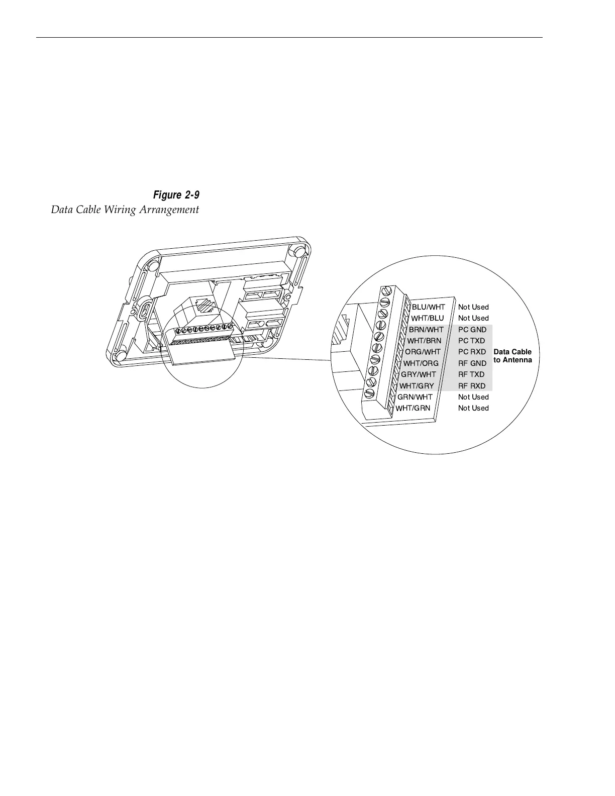
2.3.1 Wiring the Antenna Unit Data Cable
Find the TracVision 4 data cable where it comes through the
panel cutout made earlier. Wire the data cable to the switchplate
connectors as indicated in Figure 2-9. The connector board is
etched with the same wire color identification to make the wiring
process easier.
A comprehensive wiring diagram for the TracVision 4 system has
been provided in Appendix D.
2.3.2 Wiring the Antenna Unit Power Cable
Find the TracVision 4 power cable where it comes through the
panel cutout made earlier. Wire the antenna unit power cable to
the switchplate connectors as indicated in Figure 2-10 (on next
page). After wiring the power cable, connect the power indicator
lamp, also as noted in Figure 2-10. After both the power cable
and lamp are properly wired, carefully insert the lamp into its
socket immediately below the switchplate connectors.

 Loading...


