2-7
54-0150 Rev. E
Follow these steps to begin the wiring process:
1. Select a location to mount the TracVision 4
switchplate. It should be flat and within reach of
the cables connected to the Antenna Unit.
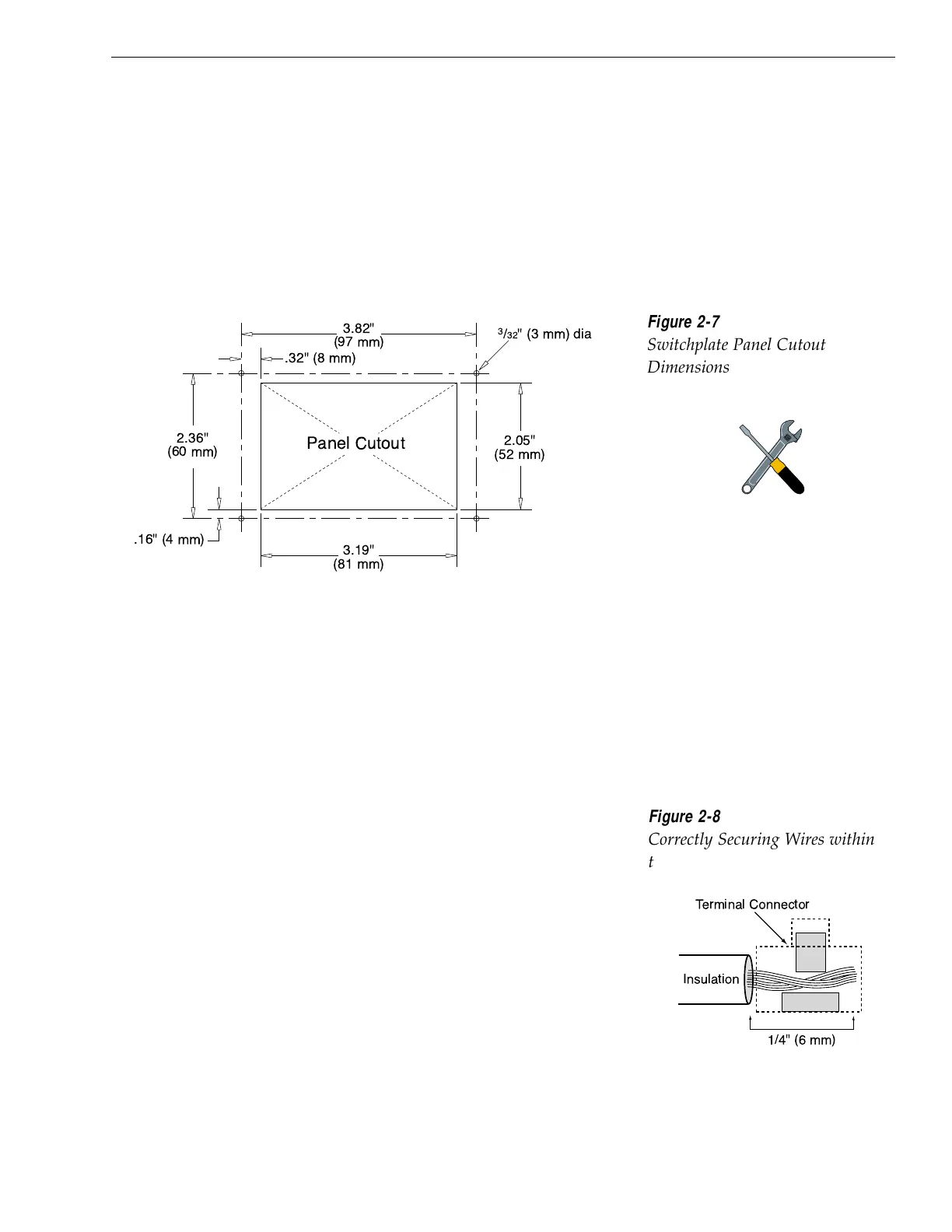
2. Create a panel cutout in the mounting surface.
Figure 2-7 illustrates the mounting dimensions
and a template has been provided in Appendix C.
3. Run the Antenna power and data cables from the
Antenna Unit and out through the panel cutout.
4. Run a cable from ship’s power (11-16 Vdc) through
the panel cutout.
You are now ready to wire the TracVision 4 system to the
switchplate connectors and ship’s power.
Tips for Safe and Successful Wiring
• When attaching cables to the TracVision 4
switchplate connectors, make sure the insulation is
stripped back approximately
3
⁄16" (5 mm). Twist the
wires gently to help achieve a good connection. Do
not pinch insulation inside the connector.
• After attaching the power and data cables to the
appropriate terminal connector strips, tug gently
to ensure a firm connection.
Installation
A full-scale panel cutout template
has been provided in Appendix C.

 Loading...


