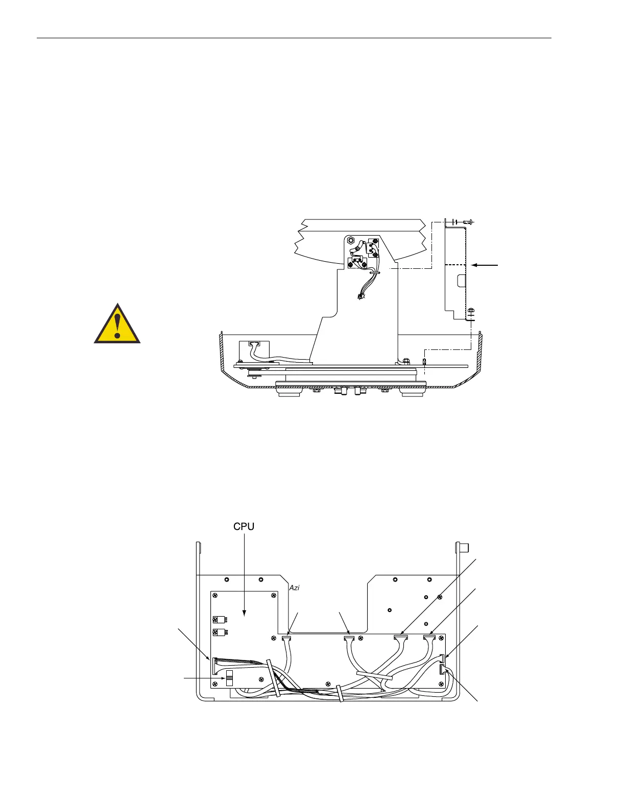
4.4 PCB Removal and Replacement
The printed circuit boards (PCBs) are protected by a cover
fastened to the antenna support frame. The cover must be
removed to gain access to the main power fuse and the
PCB assemblies discussed below. Refer to Figure 4-2; remove
(3) nuts and washers from the bottom flange and (4) screws, nuts,
and washers from the upper flange. Remove the cover and set
aside with the fasteners.
The PCBs are mounted to the antenna elevation mechanism
support frame with machine screws and are interconnected by
means of keyed Molex connectors. Figure 4-3 shows the PCB
arrangement, connector locations, and functions while Figure 4-4
on the next page shows how the printed circuit boards are
mounted to the support frame.
4-4
TracVision 4 Installation and Technical Manual
Figure 4-2
PCB Cover Plate Removal
The PCB cover fits snugly over the
PCB. When removing or replacing
the cover, take care to ensure that
the cover does not dislodge any of
the Molex connectors as this will
cause system errors and improper
operation.
Figure 4-3
PCB Connector Locations
(Rear View)

 Loading...


