The Antenna Unit printed circuit boards, Antenna LNB, elevation
stepping motor, and elevation drive belt may be removed and
replaced on site using common hand tools. Other TracVision 4
service must be done by your authorized dealer/installer,
distributor or by KVH. Evidence of tampering or unauthorized
repairs will void the warranty. The following are step-by-step
procedures for removing and replacing those components that
may be serviced.
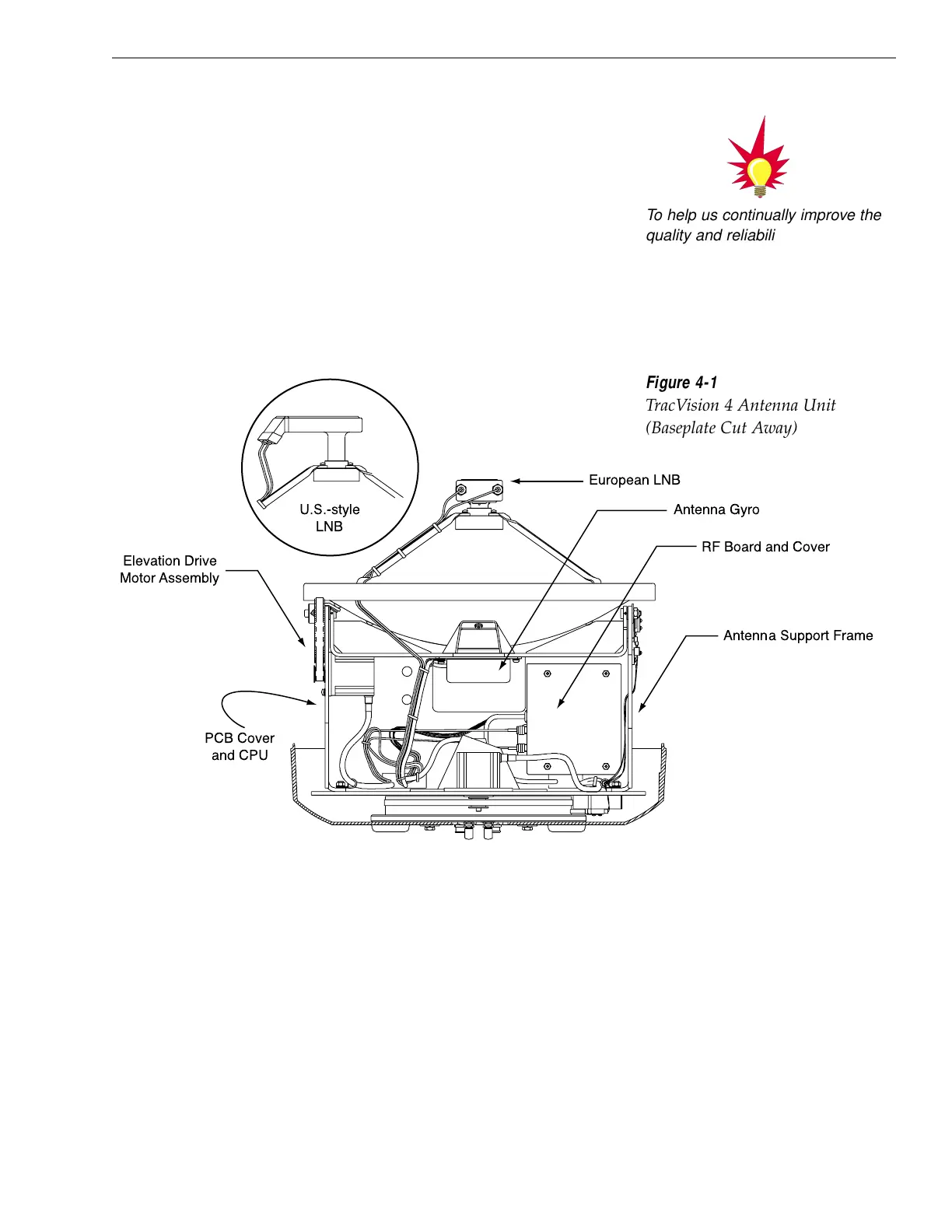
Figure 4-1 depicts the location of a number of components within
the TracVision 4 Antenna Unit.
4-3
Maintenance
54-0150 Rev. E
Figure 4-1
TracVision 4 Antenna Unit
(Baseplate Cut Away)
To help us continually improve the
quality and reliability of our
systems, please return any failed
component to KVH after you
receive your replacement part.

 Loading...


