54-0147
136
TracVision G4 Technical Manual
Option 2 - Flush Mounting
1. Using Template E-2, mark the cutout area in the
mounting surface. Cut out the marked area and
smooth the edges with a file. Test-fit the display
unit in the cutout opening.
2. Remove the two 6 mm machine screws from the
back of the display unit. Insert the display unit
into the cutout; then place the panel mounting
bracket clamp in position behind the display unit.
Reverse the 6 mm screws and reinsert into the case
through the bracket clamp. Tighten the screws to
secure in place.
E.3 Wiring the Rotating Card Display
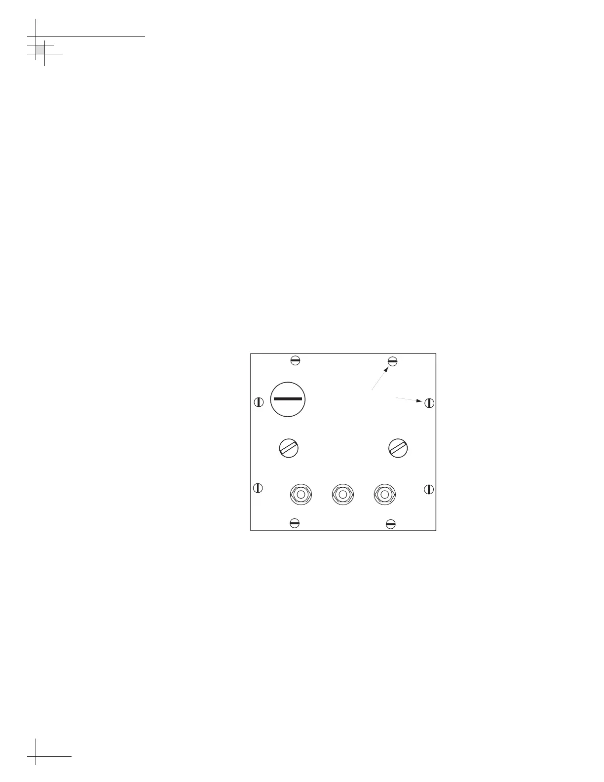
1. Refer to Figure E-2. To remove the backplate,
remove 8 screws (a) and withdraw the backplate
assembly. Separate the two pigtail plug connectors
from the card assembly.
2. Pass the power supply and data cables through
their packing glands (b, c, and d) from the outside
and tighten the gland nuts before connecting
wires.
Figure E-2
Rotating Card Display –
Removing the Backplate

 Loading...


