EasyManuals Logo

KVH Industries TracVision G4 User Manual

KVH Industries TracVision G4
155 pages
To Next Page IconTo Next Page
To Previous Page IconTo Previous Page
Page #130 background imageLoading...
Page #130 background image
Optional Rotating Card Display
54-0147
137
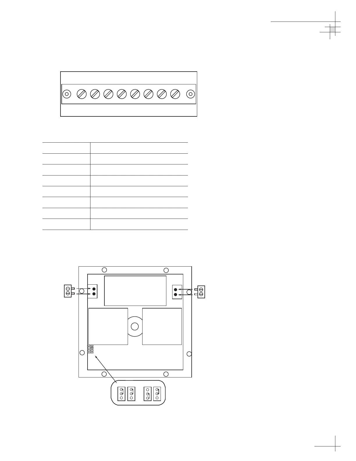
3. Refer to Figure E-3 below; connect the power and
data wires to the terminal block as listed in
Table E-1.
Term. # Function
1 Output B (linked to terminal 5)
2 Output A (linked to terminal 6)
3 Shield for output cable
4 Shield for input cable
5 Input B (NMEA 0183 data)
6 Input A (NMEA 0183 data)
7 11-40 VDC NEG (-)
8 11-40 VDC POS (+)
4. Set the jumpers as shown in Figure E-4 to select
red or green night illumination.
Table E-1
Rotating Card Display – Terminal
Strip Wiring Details
PC BOARD CONNECTORS
ILLUMINATION JUMPERS
BACKPLATE GASKET
Red
Black
1
2
Power
Supply
Plug
Red
Blue
4
3
NMEA
Data
Plug
(Red) (Green)
Figure E-4
Rotating Card Display –
PC Board Jumpers and Connectors
Figure E-3
Rotating Card Display – Terminal
Strip Wiring
1234567 8

Table of Contents

Questions and Answers:

Question and Answer IconNeed help?

Do you have a question about the KVH Industries TracVision G4 and is the answer not in the manual?

KVH Industries TracVision G4 Specifications

General IconGeneral
BrandKVH Industries
ModelTracVision G4
CategorySatellite TV System
LanguageEnglish

Related product manuals