10. Position the baseplate assembly in place over the
mounting holes and cable access, with the
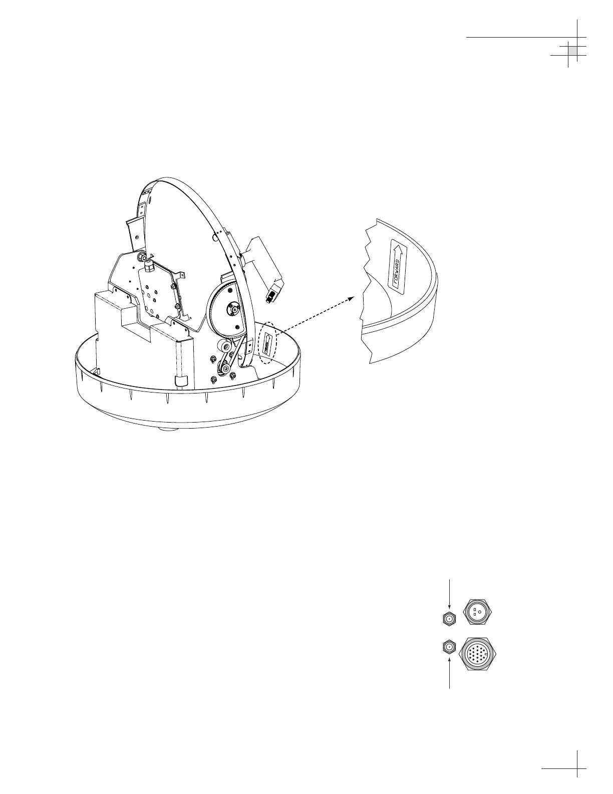
baseplate’s “Forward” arrow (shown in Figure 2-6)
pointing toward the bow. Ensure that all holes line
up and that the connectors are centered over the
cable access. Make any necessary adjustments
before seating the foam seal in place permanently.
11. Clean the mounting surface where the foam seal
will be placed. Remove the paper backing from the
foam seal to expose the contact cement, then lay
the foam seal in place, adhesive side down, and
press down firmly to bring the adhesive into full
contact along the bottom. Ensure the narrow end
points toward the bow.
12. Connect the data, power, and RF cables from
belowdecks to the baseplate as shown in
Figure 2-7. Turn the power and data cable
connectors down until locked in place; don’t use
excessive force. Connect the RF cable(s) using a
7
⁄16"
wrench, applying 30 pounds of torque. If you
connect more than one RF cable, label both ends of
each RF cable to match its antenna baseplate
connector (RF1 or RF2). Do NOT use teflon gel on
the cable fittings as it reduces signal strength at
higher frequencies.
Installation
54-0147
17
Figure 2-6
Baseplate “Forward” Arrow
Figure 2-7
Baseplate Connector Assignments
(Bottom View)

 Loading...


