13. Place the antenna baseplate over the holes drilled
in the foundation, ensuring the “Forward” label
(shown in Figure 2-6) points toward the bow.
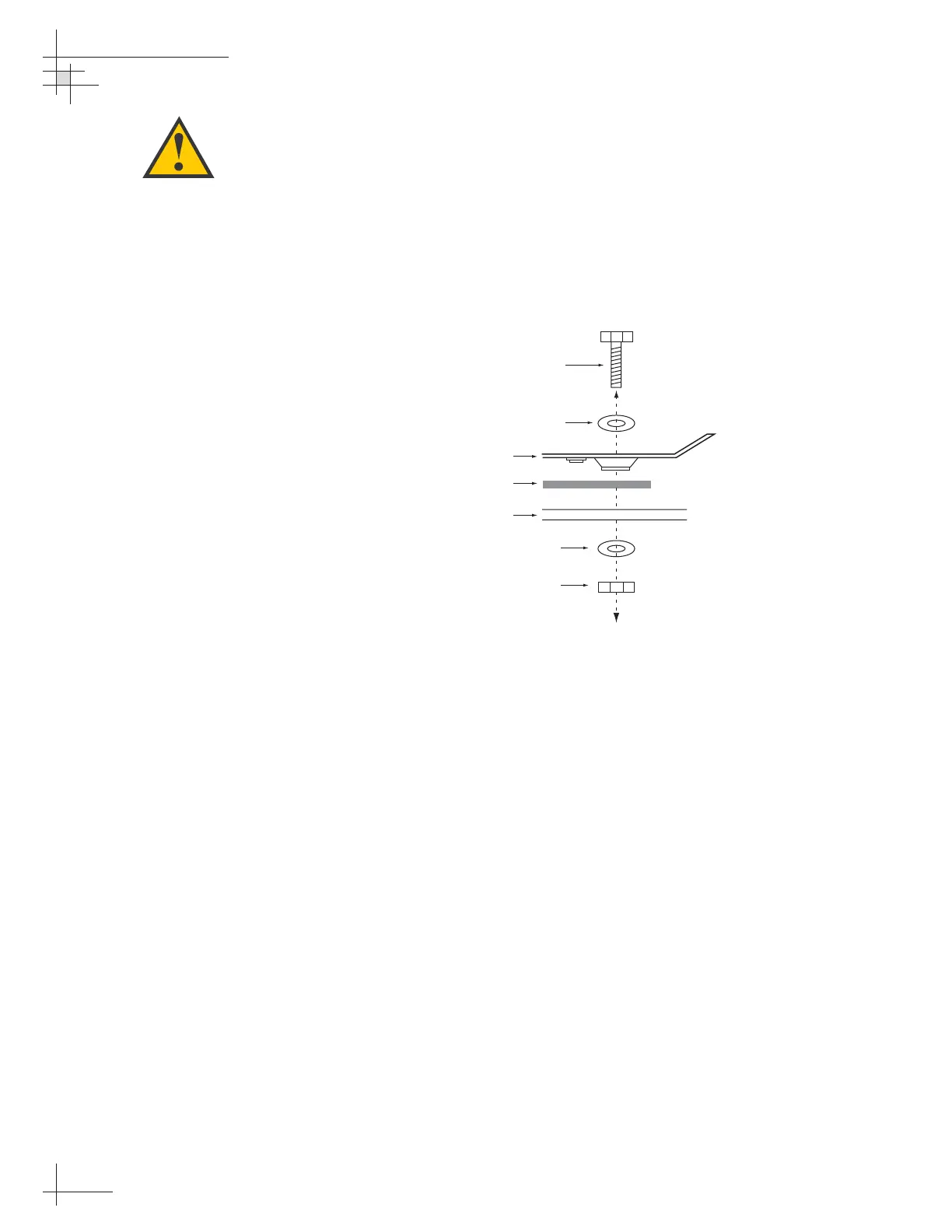
14. At each of the four baseplate mounting holes,
place a
1
⁄4" flat washer on a
1
⁄4"-20 bolt and insert the
bolt into the hole from above, as shown in
Figure 2-8. Carefully rotate the azimuth
mechanism plate to expose all four mounting
holes.
15. Apply a
1
⁄4" flat washer and
1
⁄4"-20 lock nut from
below, as shown in Figure 2-8.
16. Tighten securely (but do not overtighten) until the
foam seal is compressed as far as it will go and all
four feet are bottomed against the mounting
surface.
17. If you are installing a European system:
Leave the radome off for now; you will install it
later.
If you are installing a North American system:
Place the radome over the baseplate. Align the
three radome screw holes with the baseplate nut
holders, insert the #10-24 screws and tighten.
Install a protective plastic screw cap from the
kitpack over each screw.
Figure 2-8
Bolting the Antenna Unit to
the Deck (Side View)
When rotating the azimuth
mechanism by hand, go slowly.
Hitting the mechanical stops with
excessive force will damage the
azimuth limit switch.
54-0147
18
TracVision G4 Technical Manual
 Loading...


