15. IGNITION SYSTEM
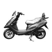
CDI UNIT
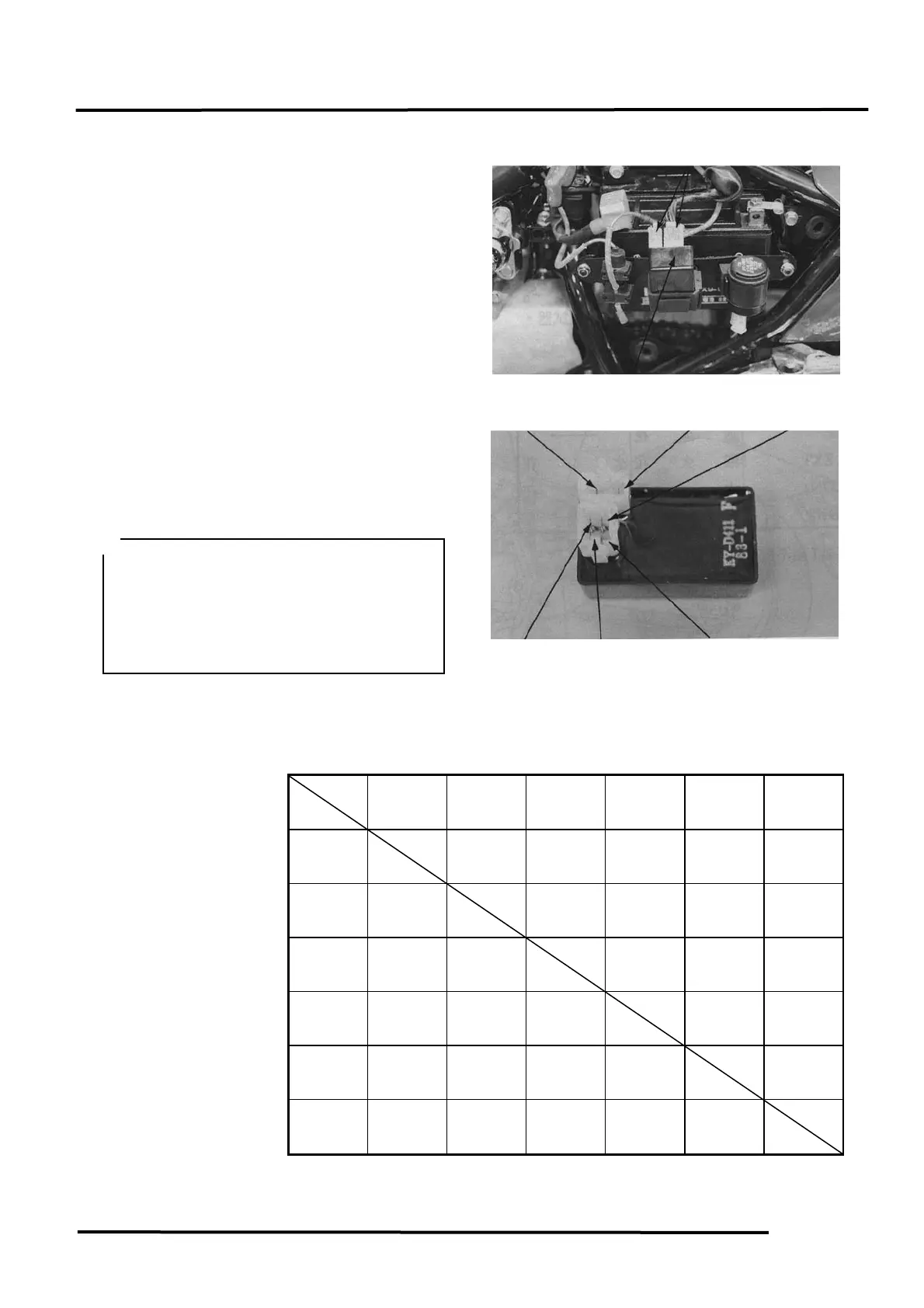
REMOVAL
Remove the left side cover.
Disconnect the CDI coupler and remove the
CDI unit.
INSPECTION
Measure the resistance between the CDI unit
terminals.
Replace the CDI unit if the readings are not
within the specifications in the table below.
Testing Range
Use the
xKΩ range for the Sanwa Tester.
Use the
x100Ω range for the Kowa Tester.
Unit: KΩ
(+)Probe
(-)Probe
SW
(Black/
White)
EXT
(Black/
Red)
PC
(Blue/
White)
E2
(Green)
E1
(Green/
White)
IGN
(Black/
Yellow)
SW
(Black/
White)
∞ ∞ ∞ ∞ ∞
EXT
(Black/
Red)
3-6K
Needle
∞
Needle
∞
∞ ∞
PC
(Blue/
White
35-42K
18-22K
8-10K 8-10K ∞
E2
(Green)
15-18K 4.5-5.5K
7-9K
There is
continuity
∞
E1
(Green/
White)
15-18K 4.5-5.5K
7-9K
There is
continuity
∞
IGN
(Black/
Yellow)
∞ ∞ ∞ ∞ ∞
Note: The readings in this table are taken with a Sanwa Tester.
nductor in circuit, it is
necessary to use a specified tester for
accurate testing. Use of an improper
tester or measurements in an improper
range may give false readings.
Use a Sanwa Electric Tester SP-100 or
Kowa Electric Tester TH-5H for testing.
Yellow)