3. LUBRICATION SYSTEM
Mounting Bolt
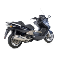
ASSEMBLY
Install the outer rotor and inner rotor into the
pump body. Insert the pump shaft.
Install the gasket and pump cover.
Tighten the screw.
After installation, make sure that the pump
shaft rotates freely.
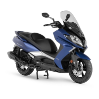
INSTALLATION
Install the pump body and tighten the two
mounting bolts.
Install the oil pump driven gear and chain.
Tighten the 6mm nut on top of the oil pump
driven gear.
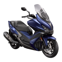
Install the oil pump gear cover and tighten
the two bolts.
Torque: 4.0~5.0kg-m
Install the right crankcase cover.
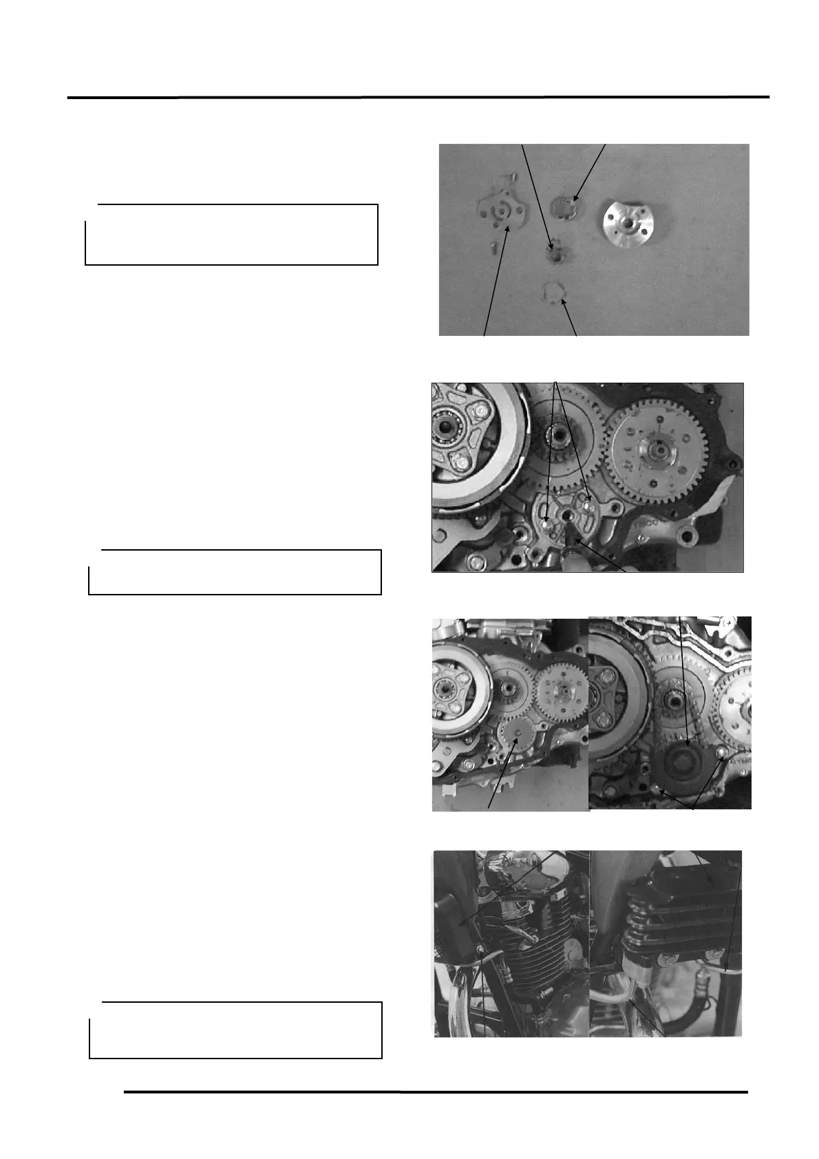
OIL PUMP/OIL FILTER ROTOR
Remove the two oil cooler protective cover
mounting bolts and remove the protective
cover.
Remove the two inlet pipe bolts and two
outlet pipe bolts.
Remove the two oil cooler attaching bolts
and oil cooler.
Check the oil cooler for damage or oil leaks.
Installation
Install the oil cooler in the reverse order of
removal.
Insert the pump shaft by aligning the flat
on the shaft with the flat in the inner
rotor.
During installation, install the washer
with the mark “OUTSIDE” facing up.
The engine oil temperature is very high.
This operation must be done when the
engine is cold to avoid burns.
 Loading...