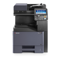
2K3/2L3
2-3-2
Connector Pin Signal I/O Voltage Description
YC100 1 VBUS O 5 V DC 5 V DC power output
Connected to
operathion
panel PWB
main(USB)
2 DATA- I/O LVDS USB data signal
3 DATA+ I/O LVDS USB data signal
4 ID - - Not used
5 GND - - Ground
YC101 1 NC - - Not used
Connected to
operation
panel PWB
main
(contorol)
2 GND - - Ground
3PANEL_STAT
US
I 0/3.3 V DC Operation panel status signal
4INT_POWER
KEY
I 0/3.3 V DC Power key: On/Off
5 PANEL_RESE
T
O 0/3.3 V DC OPPWB-M reset signal
6 AUDIO O Analog Voice output signal
7 LIGHTOFF_P
OWER
O 0/3.3 V DC Sleep return signal 1
8 SHUTDOWN O 0/3.3 V DC 24 V down signal
9 LED_PROCE
SSING
O 0/3.3 V DC Processing LED control signal
10 LED_ATTENT
ION
O 0/3.3 V DC Attention LED control signal
11 LED_MEMOR
Y
O 0/3.3 V DC Memory LED control signal
12 SUSPEND_P
ower
O 5 V DC 5 V DC power output to OPPWB-M
13 ENERGY_SA
VE
O 0/3.3 V DC Energy save signal
14 BEEP_POWE
RON
O 0/3.3 V DC Sleep return signal 0
YC102 1 5V2 O 5 V DC 5 V DC power output to OPPWB-M
Connected to
operation
panel PWB
main(power
source)
2 5V2 O 5 V DC 5 V DC power output to OPPWB-M
3 GND - - Ground
4 GND - - Ground

 Loading...


