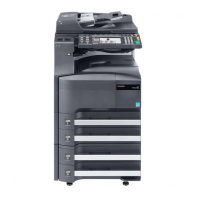
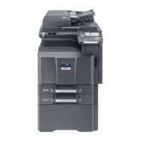
2K3/2L3
2-3-22
YC4 38 3.3V O 3.3 V DC 3.3 V DC power output to LCDRPWB
Connected to
LCD relay
PWB
39 3.3V O 3.3 V DC 3.3 V DC power output to LCDRPWB
40 3.3V O 3.3 V DC 3.3 V DC power output to LCDRPWB
YC9 1 A_LED O 0/3.3 V DC Memory LED control signal
Connected to
operation
panel PWB
left
2 M_LED O 0/3.3 V DC Attention LED control signal
3 P_LED O 0/3.3 V DC Processing LED control signal
4 KEY4 I 0/3.3 V DC(pulse) Operation panel key scan return signal 4
5INT_POWER
KEY_N
O 0/5 V DC Power key: On/Off
6 KEY3 I 0/3.3 V DC(pulse) Operation panel key scan return signal 3
7 KEY2 I 0/3.3 V DC(pulse) Operation panel key scan return signal 2
8 KEY1 I 0/3.3 V DC(pulse) Operation panel key scan return signal 1
9 LED1 O 0/3.3 V DC(pulse) Operation panel LED display drive signal
1
10 3.3V0 O 3.3V DC 3.3 V DC power output to OPPWB-L
11 LED0 O 0/3.3 V DC(pulse) Operation panel LED display drive signal
0
12 KEY0 I 0/3.3 V DC(pulse) Operation panel key scan return signal 0
13 SCAN4 O 0/3.3 V DC(pulse) Scan signal 4
14 SCAN3 O 0/3.3 V DC(pulse) Scan signal 3
15 SCAN2 O 0/3.3 V DC(pulse) Scan signal 2
16 SCAN1 O 0/3.3 V DC(pulse) Scan signal 1
17 SCAN0 O 0/3.3 V DC(pulse) Scan signal 0
18 GND - - Ground
Connector Pin Signal I/O Voltage Description

 Loading...
