26
T1
T2
T1
T2
Input Signal
Higher limit output
Lower limit output ON
OFF
ON
Higher limit
Lower limit
Hysteresis
Hysteresis
T1
T2
T3
T4
OFF
Input Signal
Higher limit output
Lower limit output ON
OFF
ON
Higher limit
Lower limit
Hysteresis
Hysteresis
T1
T2
T3
T4
OFF
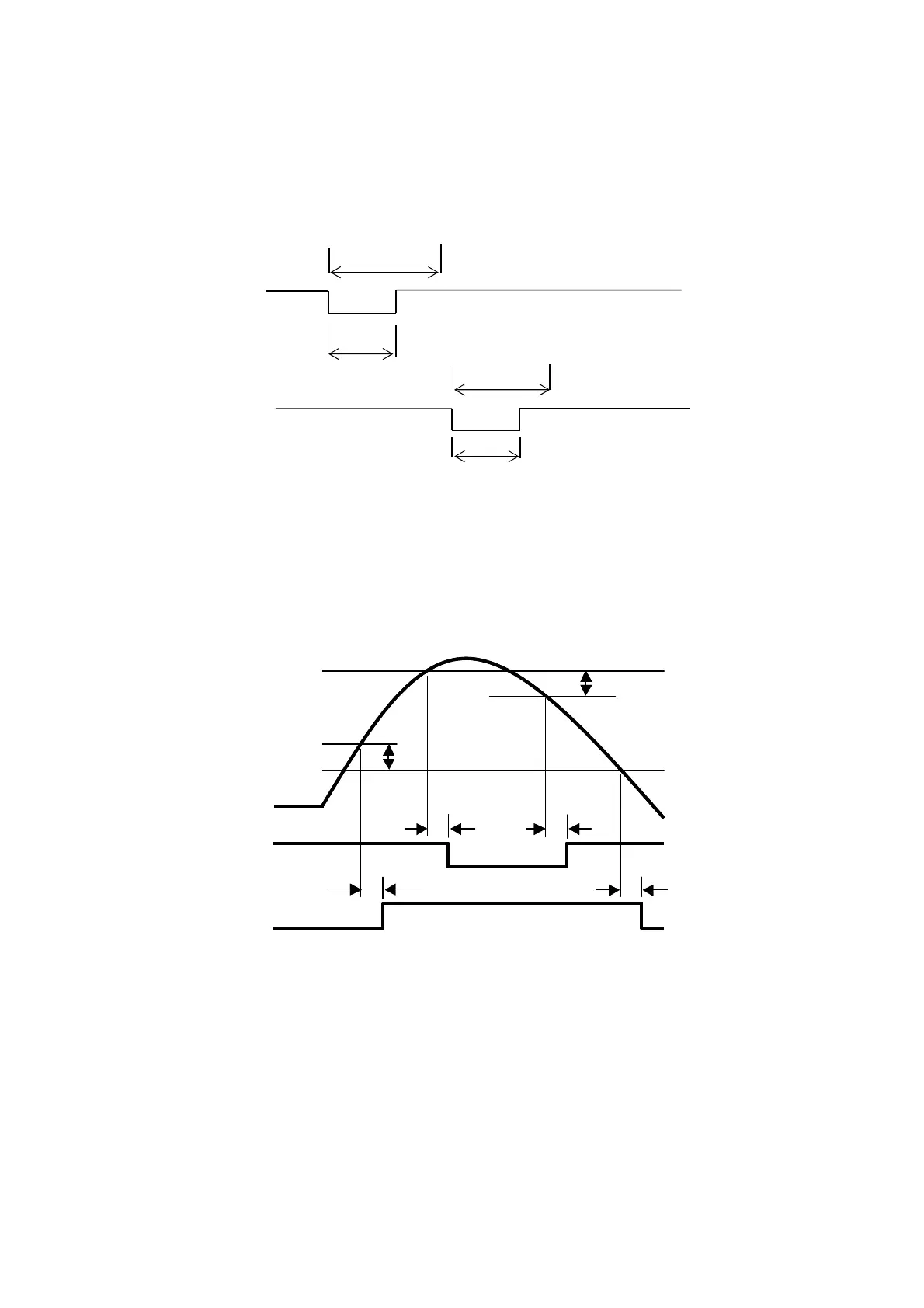
4. OPERATION TIMING
4-1 CONTROL INPUT (ZERO, LEVEL TEST, PATTERN SELECT 1, & PATTERN SELECT 2
COMMANDS)
T1: 50 ms ............ After short-circuiting the control input signal, maximum delay time until it becomes to be in
operating state.
T2: 30 ms ............ Minimum signal width of the control input signal.
4-2 HIGH/LOW COMPARATOR OUTPUT
T1: 175 ms .......... A delay time required for the high limit output to turn ON after the input value exceeds the
preset high limit comparator value.
T2: 175 ms .......... A delay time required for the high limit output to turn OFF after the input value lowers only
by the hysteresis width from the preset high limit comparator value.
T3: 175ms ........... A delay time required for the low limit output to turn OFF after the input value lowers only
by the hysteresis width from the preset low limit comparator value.
T4: 175ms ........... A delay time required for the low limit output to turn ON after the input value lowers the
preset low limit comparator value.
Zero Comman
Pattern Select Comman
Level Test Command