Lake Shore Model 331 Temperature Controller User’s Manual
5. Remove and discard both existing fuses. Replace with proper Slow-Blow (time-delay) fuse ratings
as follows:
100/120 V 1.60 A T 250 V 5 × 20 mm
220/240 V 0.80 A T 250 V 5 × 20 mm
6. Re-assemble line input assembly in reverse order.
7. Verify voltage indicator in the line input assembly window.
8. Connect instrument power cord.
9. Turn power switch On (
l).
8.4 REAR PANEL CONNECTOR DEFINITIONS
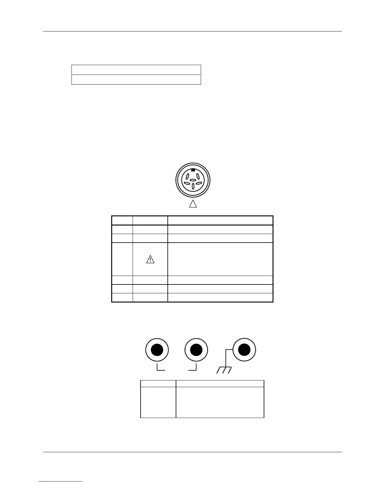
The Sensor Input, Heater Output, Relays and Analog Output, and RS-232 connectors are defined in
Figures 8-2 thru 8-5. For thermocouple connector details, refer to Figure 3-4.
I+
I
VV+
!
C331-8-2.eps
Pin Symbol Description
1 I– – Current
2 V– – Voltage
3
+1 mA – Model 330 Configuration
Shield – Model 340 Configuration
Refer to Paragraph 8.8 for jumper settings
that determine the output of this pin and to
Paragraph 3.5.1 for a general explanation.
4 V+ + Voltage
5 I+ + Current
6 None Shield
Figure 8-2. Sensor INPUT A and B Connector Details
HEATER OUTPUTHEATER OUTPUT
HIHI LOLO
60V MAX
C-331-8-3.eps
Pin Description
1
2
3
HI (Banana)
LO (Banana)
Ground (Banana)
Figure 8-3. HEATER OUTPUT Connector Details
Service 8-3