Lake Shore Model 331 Temperature Controller User’s Manual
Relays (Continued)
Relay connections are available in positions 1 thru 6 of the detachable RELAY and ANALOG OUTPUT
Terminal Block. See Figure 3-5. The terminal block (P/N 106-737) is included with the Model 331. For
convenient installation of wires, the terminal block may be removed from the socket. According to the
manufacturer, up to 12 AWG stranded copper wire may be used with the terminal block, though it is
unlikely that wire that large is required to carry the rated 5 amp current of the relay.
3.10 INITIAL SETUP AND SYSTEM CHECKOUT PROCEDURE
The following is an initial instrument setup and checkout procedure. The intent is to verify basic
operation of the unit before beginning use for measurements. The procedure assumes a setup with two
Lake Shore DT-470 Silicon Diode Sensors, one control loop, a single 50 Ω heater, all readings in
Kelvin, and running in a liquid nitrogen environment.
CAUTION: Check power source for proper voltage before connecting the line cord to the
Model 331. Also check the line voltage setting on the window in the fuse
drawer. Damage to unit may occur if connected to improper voltage.
1. Check power source for proper voltage. The Model 331 operates with 100, 120, 220, or 240
(+6%, –10%) AC input voltage.
2. Check window in fuse drawer for proper voltage setting. If incorrect, refer to Paragraph 8.2.
3. Ensure the power switch is in the off (
O) position.
CAUTION: The sensor must be connected to the rear of the unit before applying power to the
Temperature Controller. Damage to the sensor may occur if connected with power on.
4. Verify your sensor installation in the liquid nitrogen environment. Then plug the control sensor
connector in INPUT A and the sample sensor connector in INPUT B. Details of sensor hardware
connections are detailed in Paragraph 3.5.
5. Connect the heater to the banana jacks labeled HEATER OUTPUT. A 50 Ω heater allows the
maximum power output of 50 W. Details of heater installation are provided in Paragraphs 2.4
and 3.7.
6. Ensure any other rear panel connections are connected before applying power to the unit. For the
Model 331E, this includes RS-232 (Paragraph 6.2.1). For the Model 331S, this includes the
IEEE-488 (Paragraph 8.4.2), Analog Output (Paragraph 3.8), and Relays (Paragraph 3.9).
7. Plug line cord into receptacle.
8. Turn the power switch to the on (l) position. The front panel will briefly display the following.
Lake−Shore−Model−331
−−Temp.−Controller
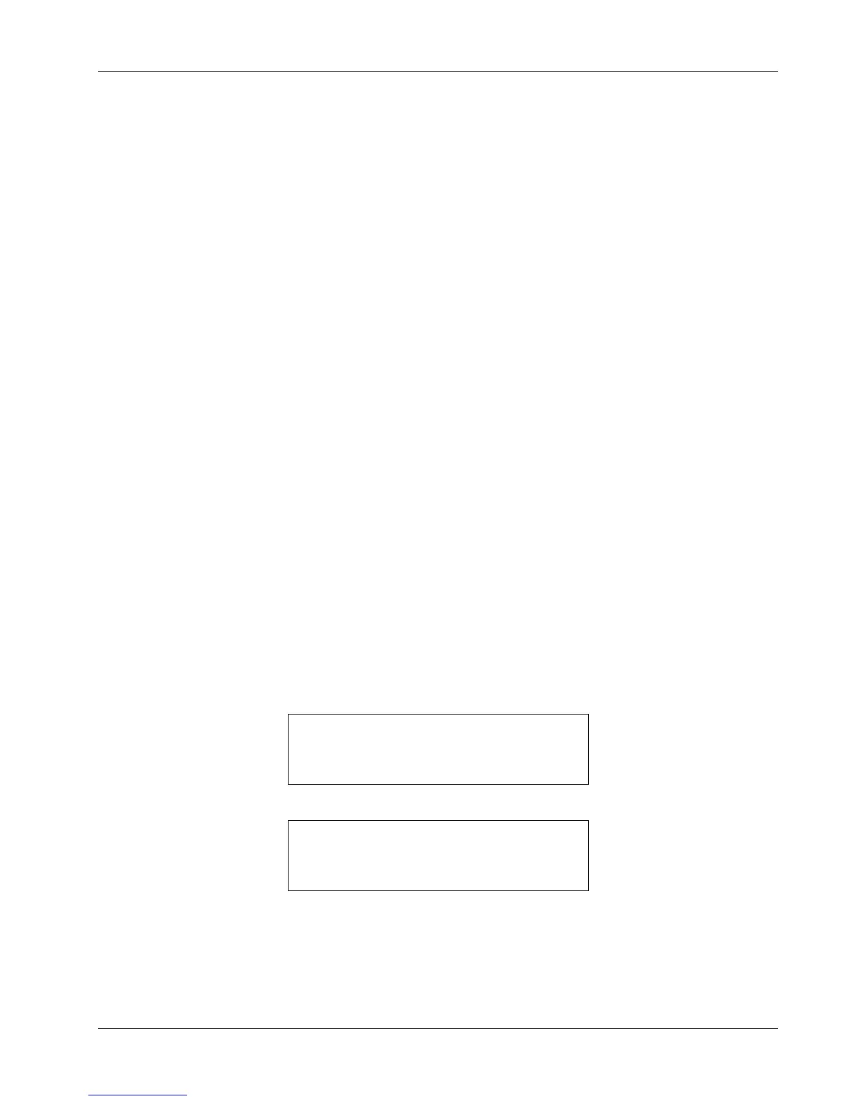
9. The typical display shown below will now appear.
À− 77.35½−Á− 77.35½
 −0.000½−−−−0%−Off
The front panel display is divided into four areas. The default display settings place the Sensor A
reading in the upper left, the Sensor B reading in the upper right, the Setpoint in the lower left, and
the heater output of Loop 1 (in percent) in the lower right. All temperature readings are in Kelvin.
Each of these display areas is individually configurable by pressing the
Display Format key and
following the instructions in Paragraph 4.3.
Installation 3-11