Lake Shore Model 331 Temperature Controller User’s Manual
3.7 HEATER OUTPUT SETUP
The following paragraphs cover the heater wiring from the vacuum shroud to the instrument for both
control loop outputs. Specifications are detailed in Paragraph 1.2. For help on choosing and installing
an appropriate resistive heater, refer to Paragraph 2.4.
3.7.1 Loop 1 Output
Of the two Model 331 control loops, Loop 1 is considered the primary loop because it is capable of
driving 50 W of heater power. The heater output for Loop 1 is a traditional control output for a
cryogenic temperature controller. It is a variable DC current source with software settable ranges and
limits. The maximum heater output current is 1 A and maximum compliance voltage is 50 V. Heater
power is applied in one of three ranges: Low, Medium, or High, as specified below.
Loop 1 Full Scale Heater Power at Typical Resistance
Heater Resistance Heater Range Heater Power
10 Ω
Low
Med
High
100 mW
1 W
10 W
25 Ω
Low
Med
High
250 mW
2.5 W
25 W
50 Ω
Low
Med
High
500 mW
5 W
50 W
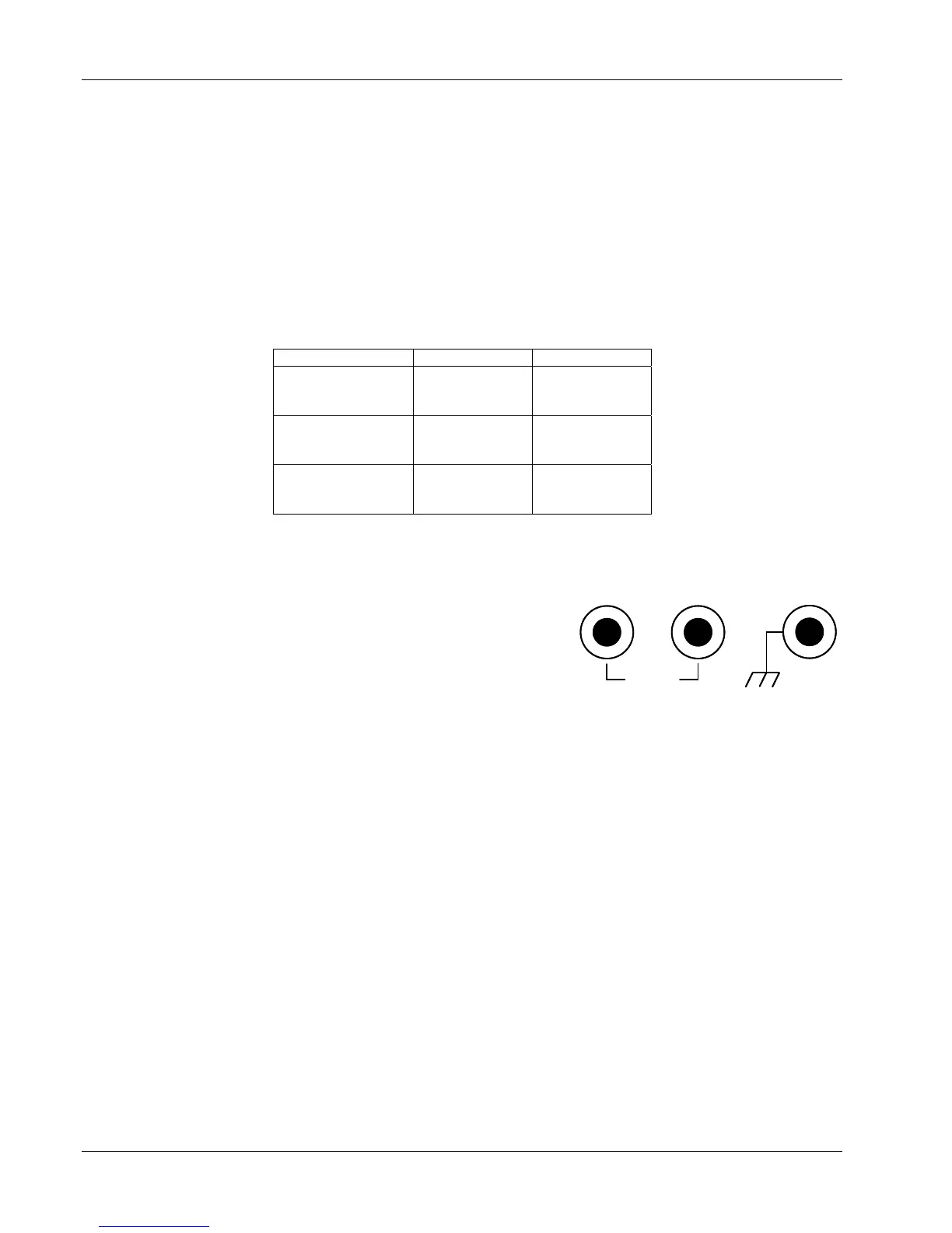
3.7.2 Loop 1 Heater Output Connector
A dual banana jack on the rear panel of the instrument is
used for connecting wires to the Loop 1 heater. A standard
dual banana plug mating connector is included in the
connector kit shipped with the instrument. This is a common
jack and additional mating connectors can be purchased from
local electronic suppliers, or from Lake Shore (P/N 106-009).
The heater is connected between the HI and LO terminals.
The ground terminal is reserved for shielding the heater leads
when necessary.
HEATER OUTPUTHEATER OUTPUT
HIHI LOLO
60V MAX
3.7.3 Loop 1 Heater Output Wiring
Heater output current is what determines the size (gauge) of wire needed to connect the heater. The
maximum current that can be sourced from the Loop 1 heater output is 1 A. When less current is
needed to power a cooling system it can be limited with range settings.
When setting up a temperature control system, the lead wire for the heater be capable of carrying a
continuous current that is greater than the maximum current. Wire manufactures recommend
30 AWG or larger wire to carry 1 A of current, but there is little advantage in using wire smaller than
20 to 22 AWG outside the cryostat. Inside the cryostat, smaller gauge wire is often desirable.
It is recommended to use twisted heater leads. Large changes in heater current can induce noise in
measurement leads and twisting reduces the effect. It is also recommended to run heater leads in a
separate cable from the measurement leads to further reduce interaction.
There is a chassis ground point at the rear panel of the instrument for shielding the heater cable. The
cable shield can be tied to this point with a single banana plug. The shield should not be connected at
the opposite end of the cable and should never be tied to the heater output leads.
The Loop 1 heater output is isolated from chassis ground to reduce noise. For best noise
performance, do not connect the resistive heater or its leads to ground. Also avoid connecting heater
leads to sensor leads or any other instrument inputs or outputs.
3-8 Installation