Lake Shore Model 331 Temperature Controller User’s Manual
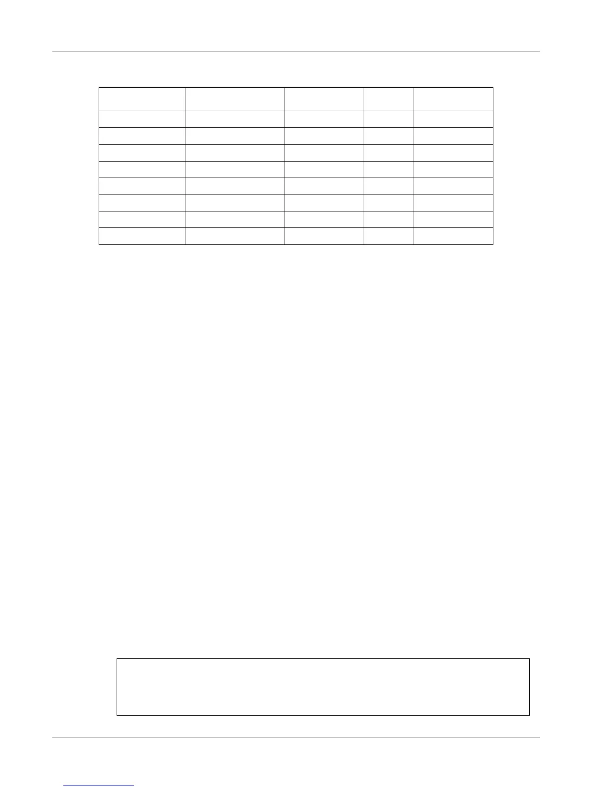
Table 8-2. Calibration Table for Resistive Ranges
Range
Calibration Resistor
Nominal Value
Resistor Value
Known to
Reversal
Cal. Command
Type Number
100 Ω Plat/250 100 Ω ±0.0070 Ω
Off 2
100 Ω Plat/250 100 Ω ±0.0070 Ω
On 10
100 Ω Plat/500 500 Ω ±0.0270 Ω
Off 3
100 Ω Plat/500 500 Ω ±0.0270 Ω
On 11
1000 Ω Plat 5 kΩ ±0.520 Ω
Off 4
1000 Ω Plat 5 kΩ ±0.520 Ω
On 12
NTC RTD
5 kΩ ±0.520 Ω
Off 5
NTC RTD
5 kΩ ±0.520 Ω
On 13
8.9.3 Diode Sensor Input Calibration – 1 mA Excitation Current
The instrument uses the calibration constants determined in the Diode Input Ranges Calibration
(Paragraph 8.9.2.3), for the diode ranges that use 1 mA excitation. Therefore, no additional
calibration is necessary.
NOTE: Standard diode curves and typical sensor performance (Table 1-2) are calculated
using 10 µA excitation. Sensor temperature response characteristics will be
altered if 1 mA excitation is selected.
8.9.4 Thermocouple Sensor Input Calibration
Overview
Each thermocouple sensor input requires calibration. The sensor inputs contain multiple gain stages
to accommodate the various thermocouple sensors the Model 331 supports. The input circuitry is not
adjusted during calibration. Instead, precision voltages are supplied to each input and mathematical
calibration constants are calculated and programmed into the Model 331. Constants are stored to
compensate for both input offset and gain errors. Thermocouple inputs do not use the current source.
Calibration Process
8.9.4.1 Sensor Input Calibration Setup
Allow the Model 331 to warm up for at least 1 hour with shorts placed across all thermocouple
sensor inputs. If calibrating a dual thermocouple Model 331, leave a short across the input not
currently being calibrated. If the other input is diode/resistor, place a 100 kΩ resistor on the input.
CAUTION: All thermocouple connections must be tight and direct with no unnecessary
jumpers or connections.
8.9.4.2 Thermocouple Input Ranges Calibration
Purpose
To determine the input offset and gain errors when the input is configured for the thermocouple
ranges and provide offset and gain calibration constants back to the Model 331.
Process
1. Configure the input for the thermocouple range to be calibrated. Turn Room Cal off.
2. Reset the calibration constants to their default values using the
CALRSTZ and CALRSTG
commands.
EXAMPLE:
Input: A
Range: Thermo/25mV
Zero Offset Reset Command:
CALRSTZ A,6
Gain Reset Command:
CALRSTG A,6
8-14 Service