Lake Shore Model 332 Temperature Controller User’s Manual
8.4.1 Serial Interface Cable Wiring
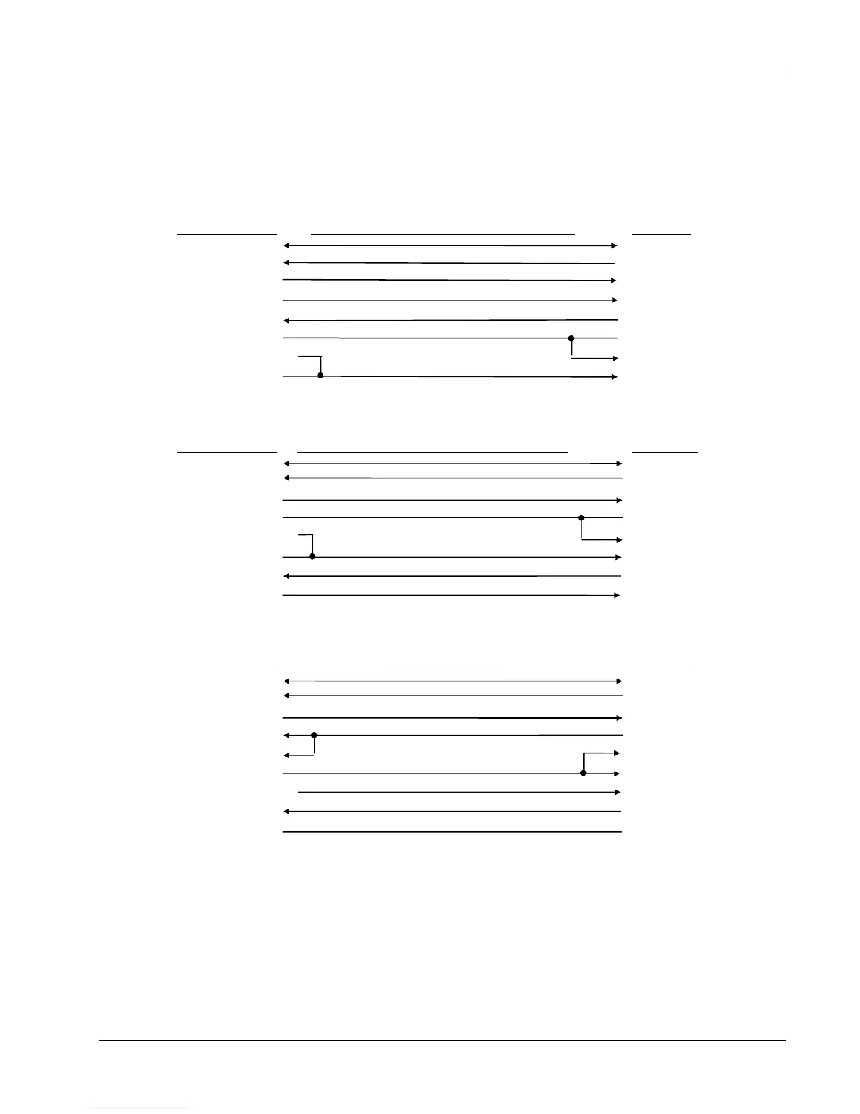
The following are suggested cable wiring diagrams for connecting the Model 332 Serial Interface to
various Customer Personal Computers (PCs).
Model 332 to PC Serial Interface – PC with DE-9P
Model 332 DE-9P Standard Null-Modem Cable (DE-9S to DE-9S) PC DE-9P
5 - GND 5 - GND
2 - RD (in) 3 - TD (out)
3 - TD (out) 2 - RD (in)
4 - DTR (out) 6 - DSR (in)
6 - DSR (in) 4 - DTR (out)
1 - NC 7 - RTS (out)
7 - DTR (tied to 4) 8 - CTS (in)
8 - NC 1 - DCD (in)
Model 332 to PC Serial Interface – PC with DB-25P
Model 332 DE-9P Standard Null-Modem Cable (DE-9S to DB-25S) PC DB-25P
5 - GND 7 - GND
2 - RD (in) 2 - TD (out)
3 - TD (out) 3 - RD (in)
1 - NC 4 - RTS (out)
7 - DTR (tied to 4) 5 - CTS (in)
8 - NC 8 - DCD (in)
6 - DSR (in) 20 - DTR (out)
4 - DTR (out) 6 - DSR (in)
Model 332 to PC Interface using Null Modem Adapter
Model 332 DE-9P Null Modem Adapter PC DE-9P
5 - GND 5 - GND
2 - RD (in) 3 - TD (out)
3 - TD (out) 2 - RD (in)
1 - NC 4 - DTR (out)
6 - DSR (in) 1 - DCD (in)
4 - DTR (out) 6 - DSR (in)
7 - DTR (tied to 4) 8 - CTS (in)
8 - NC 7 - RTS (out)
9 - NC 9 - NC
NOTE: Same as null modem cable design except PC CTS is provided from the
Model 332 on DTR.
Service 8-5
 Loading...


